


5-14
Cisco Intrusion Prevention System Appliance and Module Installation Guide for IPS 7.1
OL-24002-01
Chapter 5 Installing the IPS 4270-20
Diagnostic Panel
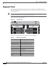
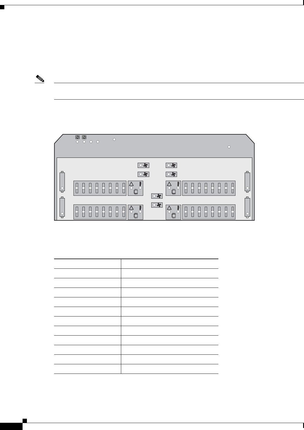
Diagnostic Panel
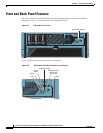
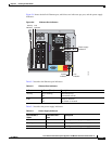
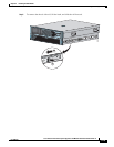
The front panel health indicators only indicate the current hardware status. The Diagnostic Panel
indicators identify components experiencing an error, event, or failure. All indicators are off unless one
of the component fails.
Note
When you remove the chassis cover to view the Diagnostic Panel, leave the IPS 4270-20 powered on.
Powering off the IPS 4270-20 clears the Diagnostic Panel indicators.
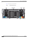
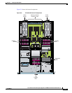
Figure 5-10 shows the Diagnostic Panel.
Figure 5-10 Diagnostic Panel
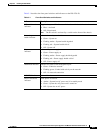
Table 5-4 lists the indicators that display health status for each component:
!
PROC1
FAN5
FAN6
FAN3
FAN4
FAN1
FAN2
!
PROC2
!
PROC3
!
PROC4
POWER
FAULT
PS1
PS2
CPU BD
I/O BD
NMI
INTERLOCK
ERROR
CPU BD
9A
10A
11B
12B
13C
14C
15D
16D
25A
26A
27B
28B
29C
30C
31D
32D
PPM2PPM4
PPM1PPM3
8D
7D
6C
5C
4B
3B
2A
1A
24D
23D
22C
21C
20B
19B
18A
17A
MEMORY
MEMORY
250250
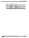
Table 5-4 Diagnostic Panel Indicators
Indicator Component
PS1 Power supply (primary)
PS2 Power supply (optional)
CPU BD (power fault) Processor memory module board
I/O BD System board
NMI System NMI switch
Slot X Expansion slot
CPU BD (interlock error) System board
PPM X Processor power module
1A-32D DIMM Slot
PROC X Processor
FAN X Fan