


6-20
Cisco Intrusion Prevention System Appliance and Module Installation Guide for IPS 7.1
OL-24002-01
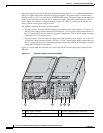
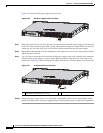
Chapter 6 Installing the IPS 4345 and IPS 4360
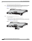
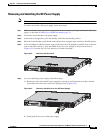
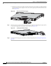
Removing and Installing the Power Supply
Installing DC Input Power
Warning
The covers are an integral part of the safety design of the product. Do not operate the unit without the
covers installed.
Statement 1077
Warning
When you install the unit, the ground connection must always be made first and disconnected last.
Statement 1046
Warning
Before performing any of the following procedures, ensure that power is removed from the DC circuit.
Statement 1003
Warning
Only trained and qualified personnel should be allowed to install, replace, or service this equipment.
Statement 1030
Warning
This product relies on the building’s installation for short-circuit (overcurrent) protection. Ensure that
the protective device is rated not greater than: 80 VAC, 20A.
Statement 1005
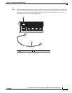
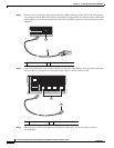
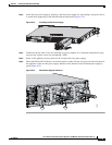
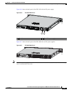
The DC power supply is shipped installed in the chassis, either one or two power supplies depending on
which configuration you ordered. You must connect the power supply wires. This section describes how
to install the DC power supply ground leads and input power leads to the appliance DC input power
supply. Before you begin, read these important notices:
•
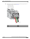
The color coding of the DC input power supply leads depends on the color coding of the DC power
source at your site. Typically, green or green/yellow is used for ground (GND), black is used for –48
V on the negative (–) terminal, and red is used for RTN on the positive (+) terminal. Ensure that the
lead color coding you choose for the DC input power supply matches the lead color coding used at
the DC power source.
•
Make sure that the chassis ground is connected on the chassis before you begin installing the DC
power supply. For more information, see Working in an ESD Environment, page 2-4.