


7-11
Cisco Intrusion Prevention System Appliance and Module Installation Guide for IPS 7.1
OL-24002-01
Chapter 7 Installing the IPS 4510 and IPS 4520
Installing the IPS 4510 and IPS 4520
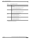
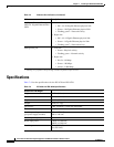
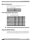
Table 7-7 lists the SFP/SFP+ modules that the IPS 4510 and IPS 4520 support.
Installing the IPS 4510 and IPS 4520
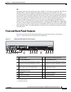
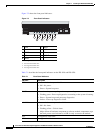
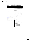
The IPS 4510 and IPS 4520 have two dedicated Gigabit Ethernet interfaces for device management that
are called Management 0/0 and Management 0/1. The additional interface, Management 0/1 is reserved
for future use. The management interfaces are similar to the console port, because they only accept
traffic that is destined to-the-box (versus traffic that is through-the-box).
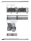
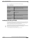
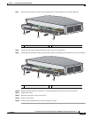
To connect the IPS 4510 and IPS 4520 cables to the network interfaces, follow these steps:
Step 1
Place the sensor on a flat, stable surface, or in a rack (if you are rack-mounting it).
Step 2
Connect to the management interface, Management 0/0.
a.
Locate an Ethernet cable, which has an RJ-45 connector on each end.
Table 7-7 SFP/SFP+ Modules
1G SFP Module
GLC-SX-MM 1000 Base-SX SFP module
GLC-SX-MMD 1000BASE-SX short wavelength, with DOM
GLC-LH-SM 1000 Base-LX/LH SFP module
GLC-LH-SMD 1000BASE-LX/LH long-wavelength, with DOM
GLC-T 1000BASE-T standard
10G SFP+ Module
SFP-10G-ER 10G ER SFP+ module
SFP-10G-SR 10G SR SFP+ module
SFP-10G-LRM 10G LRM SFP+ module
SFP-10G-LR 10G LR SFP+ module
SFP-H10GB-ACU7M 10GBASE-CU SFP+ Cable 7 Meter, active
SFP-H10GB-ACU10M 10GBASE-CU SFP+ Cable 10 Meter, active
SFP-H10GB-CU1M 10GBASE-CU SFP+ cable 1 meter, passive
SFP-H10GB-CU3M 10GBASE-CU SFP+ cable 3 meter, passive
SFP-H10GB-CU5M 10GBASE-CU SFP+ cable 5 meter, passive