


B-9
Cisco Intrusion Prevention System Appliance and Module Installation Guide for IPS 7.1
OL-24002-01
Appendix B Initializing the Sensor
Advanced Setup
Note
The following options let you create and delete interfaces. You assign the interfaces to virtual
sensors in the virtual sensor configuration. If you are using promiscuous mode for your
interfaces and are not subdividing them by VLAN, no additional configuration is necessary.
[1] Remove interface configurations.
[2] Add/Modify Inline Vlan Pairs.
[3] Add/Modify Promiscuous Vlan Groups.
[4] Add/Modify Inline Interface Pairs.
[5] Add/Modify Inline Interface Pair Vlan Groups.
[6] Modify interface default-vlan.
Option:
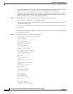
Step 8
Enter
2
to add inline VLAN pairs and display the list of available interfaces.
Caution
The new VLAN pair is not automatically added to a virtual sensor.
Available Interfaces
[1] GigabitEthernet0/0
[2] GigabitEthernet0/1
[3] GigabitEthernet0/2
[4] GigabitEthernet0/3
Option:
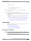
Step 9
Enter
1
to add an inline VLAN pair to GigabitEthernet 0/0, for example.
Inline Vlan Pairs for GigabitEthernet0/0
None
Step 10
Enter a subinterface number and description.
Subinterface Number:
Description[Created via setup by user asmith]:
Step 11
Enter numbers for VLAN 1 and 2.
Vlan1[]: 200
Vlan2[]: 300
Step 12
Press Enter to return to the available interfaces menu.
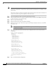
Note
Entering a carriage return at a prompt without a value returns you to the previous menu.
[1] GigabitEthernet0/0
[2] GigabitEthernet0/1
[3] GigabitEthernet0/2
[4] GigabitEthernet0/3
Option:
Note
At this point, you can configure another interface, for example, GigabitEthernet 0/1, for inline
VLAN pair.
Step 13
Press Enter to return to the top-level interface editing menu.
[1] Remove interface configurations.
[2] Add/Modify Inline Vlan Pairs.