


5-36
Cisco Intrusion Prevention System Appliance and Module Installation Guide for IPS 7.1
OL-24002-01
Chapter 5 Installing the IPS 4270-20
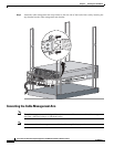
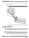
Installing the IPS 4270-20
with standard practices for preventing accidents. Use the statement number provided at the end of
each warning to locate its translation in the translated safety warnings that accompanied this device.
Statement 1071
SAVE THESE INSTRUCTIONS
Warning
Only trained and qualified personnel should be allowed to install, replace, or service this equipment.
Statement 1030
To install the IPS 4270-20 on the network, follow these steps:
Step 1
Position the IPS 4270-20 on the network.
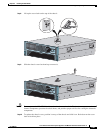
Step 2
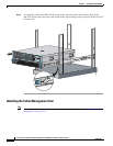
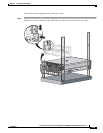
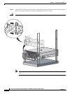
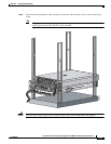
Install the IPS 4270-20 in a rack, if you are rack mounting it.
Step 3
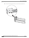
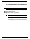
Connect the cable as shown in Step 4 so that you have either a DB-9 connector on one end as required
by the serial port for your computer, and the other end is the RJ-45 connector.
Note
Use the console port to connect to a computer to enter configuration commands. Locate the serial
cable from the accessory kit. The serial cable assembly consists of a 180/rollover cable with
RJ-45 connectors (DB-9 connector adapter PN 74-0495-01).
Note
You can use a 180/rollover or straight-through patch cable to connect the appliance to a port on
a terminal server with RJ-45 or hydra cable assembly connections. Connect the appropriate cable
from the console port on the appliance to a port on the terminal server.