


F-3
Cisco Intrusion Prevention System Appliance and Module Installation Guide for IPS 7.1
OL-24002-01
Appendix F Cable Pinouts
RJ-45 to DB-9 or DB-25
Examine the sequence of colored wires to determine the type of RJ-45 cable, as follows:
•
Straight-through—The colored wires are in the same sequence at both ends of the cable.
•
Cross-over—The first (far left) colored wire at one end of the cable is the third colored wire at the
other end of the cable.
•
Roll-over—The colored wires are in the opposite sequence at either end of the cable.
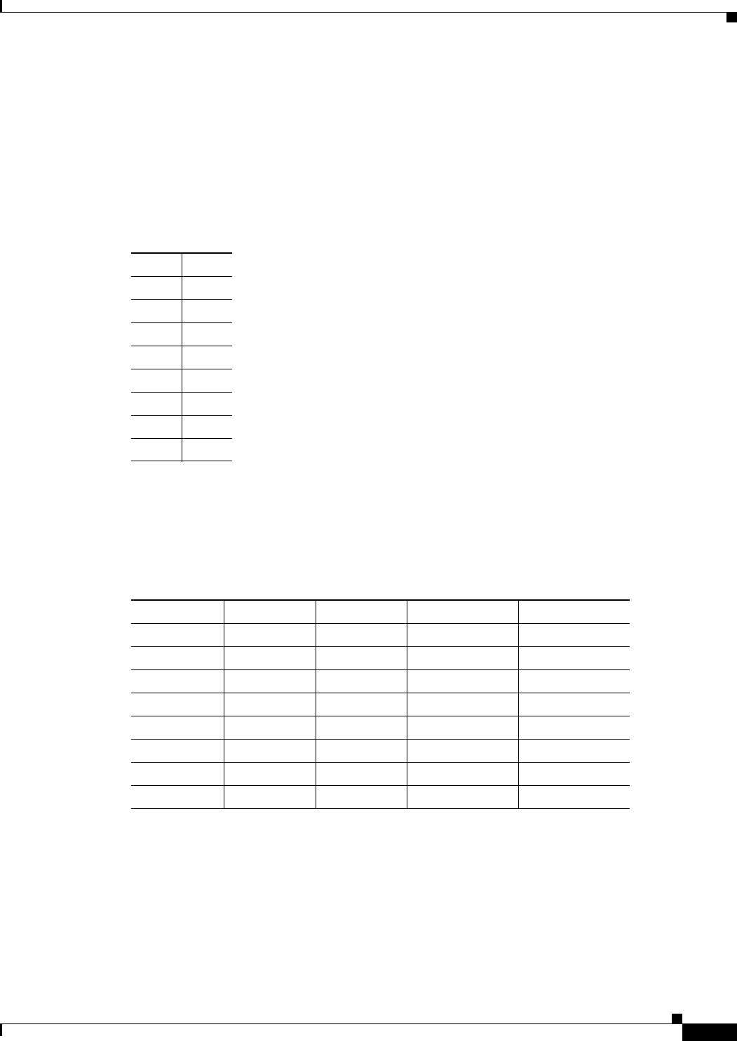
Table F-1 lists the roll-over (console) cable pinouts for RJ-45.
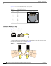
RJ-45 to DB-9 or DB-25
Table F-2 lists the cable pinouts for RJ-45 to DB-9.
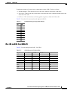
Table F-1 RJ-45 Roll-Over (Console) Cable Pinouts
Pin Pin
18
27
36
45
54
63
72
81
Table F-2 Cable Pinouts for RJ-45 to DB-9
Signal Console Port RJ-45 Pin DB-9 Pin Signal
RTS 1 8 7 CTS
DTR 2 7 4 DSR
TxD 3 6 3 RxD
GND 4 5 5 GND
GND 5 4 5 GND
RxD 6 3 2 TxD
DSR 7 2 6 DTR
CTS 8 1 8 RTS