


1-4
Cisco Intrusion Prevention System Appliance and Module Installation Guide for IPS 7.1
OL-24002-01
Chapter 1 Introducing the Sensor
How the Sensor Functions
•
Filter out known false positives caused by specialized software, such as vulnerability scanner and
load balancers by one of the following methods:
–
You can configure the sensor to ignore the alerts from the IP addresses of the scanner and load
balancer.
–
You can configure the sensor to allow these alerts and then use the IME to filter out the false
positives.
•
Filter the Informational alerts.
These low priority events notifications could indicate that another device is doing reconnaissance
on a device protected by the IPS. Research the source IP addresses from these Informational alerts
to determine what the source is.
•
Analyze the remaining actionable alerts:
–
Research the alert.
–
Fix the attack source.
–
Fix the destination host.
–
Modify the IPS policy to provide more information.
For More Information
•
For a detailed description of risk rating, refer to Calculating the Risk Rating.
•
For information on Cisco signatures, for the IDM and IME refer to Defining Signatures, and for the
CLI refer to Defining Signatures.
•
For detailed information on event action overrides, for the IDM and IME refer to Configuring Event
Action Overrides, and for the CLI, refer to Configuring Event Action Overrides.
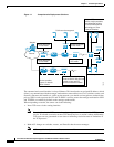
Sensor Interfaces
This section describes the sensor interfaces, and contains the following topics:
•
Understanding Sensor Interfaces, page 1-4
•
Command and Control Interface, page 1-5
•
Sensing Interfaces, page 1-6
•
Interface Support, page 1-6
•
TCP Reset Interfaces, page 1-11
•
Interface Restrictions, page 1-12
Understanding Sensor Interfaces
The sensor interfaces are named according to the maximum speed and physical location of the interface.
The physical location consists of a port number and a slot number. All interfaces that are built-in on the
sensor motherboard are in slot 0, and the interface card expansion slots are numbered beginning with
slot 1 for the bottom slot with the slot numbers increasing from bottom to top (except for the
IPS 4270-20, where the ports are numbered from top to bottom). Each physical interface can be divided
in to VLAN group subinterfaces, each of which consists of a group of VLANs on that interface.