


8-6
Cisco Intrusion Prevention System Appliance and Module Installation Guide for IPS 7.1
OL-24002-01
Chapter 8 Installing and Removing the ASA 5500 AIP SSM
Installation and Removal Instructions
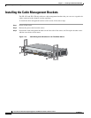
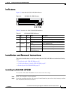
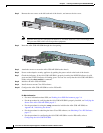
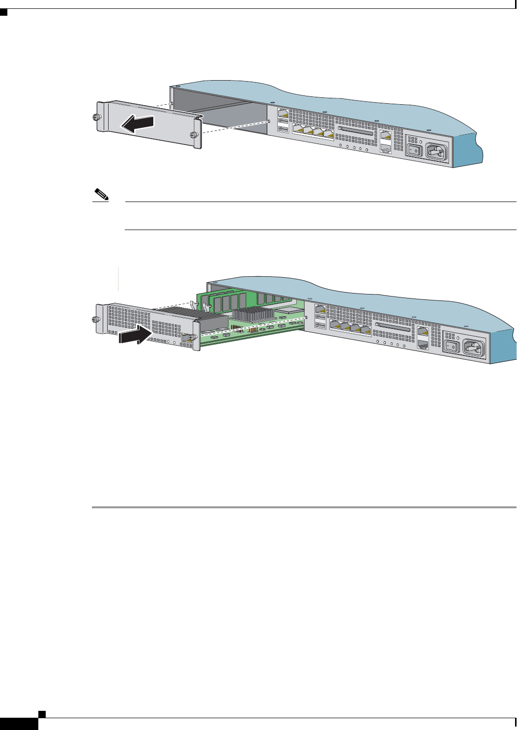
Step 3
Remove the two screws at the left back end of the chassis, and remove the slot cover.
Note
Store the slot cover in a safe place for future use. You must install slot covers on all empty slots.
This prevents EMI, which can disrupt other equipment.
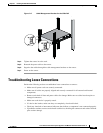
Step 4
Insert the ASA 5500 AIP SSM through the slot opening.
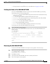
Step 5
Attach the screws to secure the ASA 5500 AIP SSM to the chassis.
Step 6
Power on the adaptive security appliance by pushing the power switch at the back of the chassis.
Step 7
Check the indicators. If the ASA 5500 AIP SSM is properly installed, the POWER indicator is solid
green and the STATUS indicator is flashing green. You can also verify that the ASA 5500 AIP SSM is
online using the show module 1 command.
Step 8
Initialize the ASA 5500 AIP SSM.
Step 9
Install the most recent Cisco IPS software.
Step 10
Configure the ASA 5500 AIP SSM to receive IPS traffic.
For More Information
•
For more information about ESD, see Working in an ESD Environment, page 2-4.
•
For the procedure for verifying that the ASA 5500 AIP SSM is properly installed, see Verifying the
Status of the ASA 5500 AIP SSM, page 8-7.
•
For the procedure for using the setup command to initialize the ASA 5500 AIP SSM, see
Appendix B, “Initializing the Sensor.”.
•
For the procedure for obtaining the latest Cisco IPS software, see Obtaining Cisco IPS Software,
page C-1.
•
For the procedure for configuring the ASA 5500 AIP SSM to receive IPS traffic, refer to
Configuring the ASA 5500 AIP SSM.
250246
L
IN
K
S
P
D
3
L
IN
K
S
P
D
2
L
I
N
K
S
P
D
1
L
I
N
K
S
P
D
0
MGMT
USB2
USB1
F
L
A
S
H
POWER
STATUS
FLASH
VPN
ACTIVE
P
W
R
S
T
A
T
U
S
S
P
E
E
D
L
IN
K
/A
C
T
L
I
N
K
S
P
D
3
L
I
N
K
S
P
D
2
L
I
N
K
S
P
D
1
L
I
N
K
S
P
D
0
MGMT
USB2
USB1
POWER
STA
TUS
FLASH
VPN
ACTIVE
L
I
N
K
S
P
D
3
L
I
N
K
S
P
D
2
L
I
N
K
S
P
D
1
L
I
N
K
S
P
D
0
MGMT
USB2
USB1
F
L
A
S
H
POWER
STATUS
FLASH
VPN
ACTIVE