


9-5
Cisco Intrusion Prevention System Appliance and Module Installation Guide for IPS 7.1
OL-24002-01
Chapter 9 Installing and Removing the ASA 5585-X IPS SSP
Front Panel Features
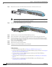
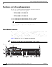
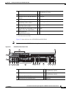
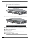
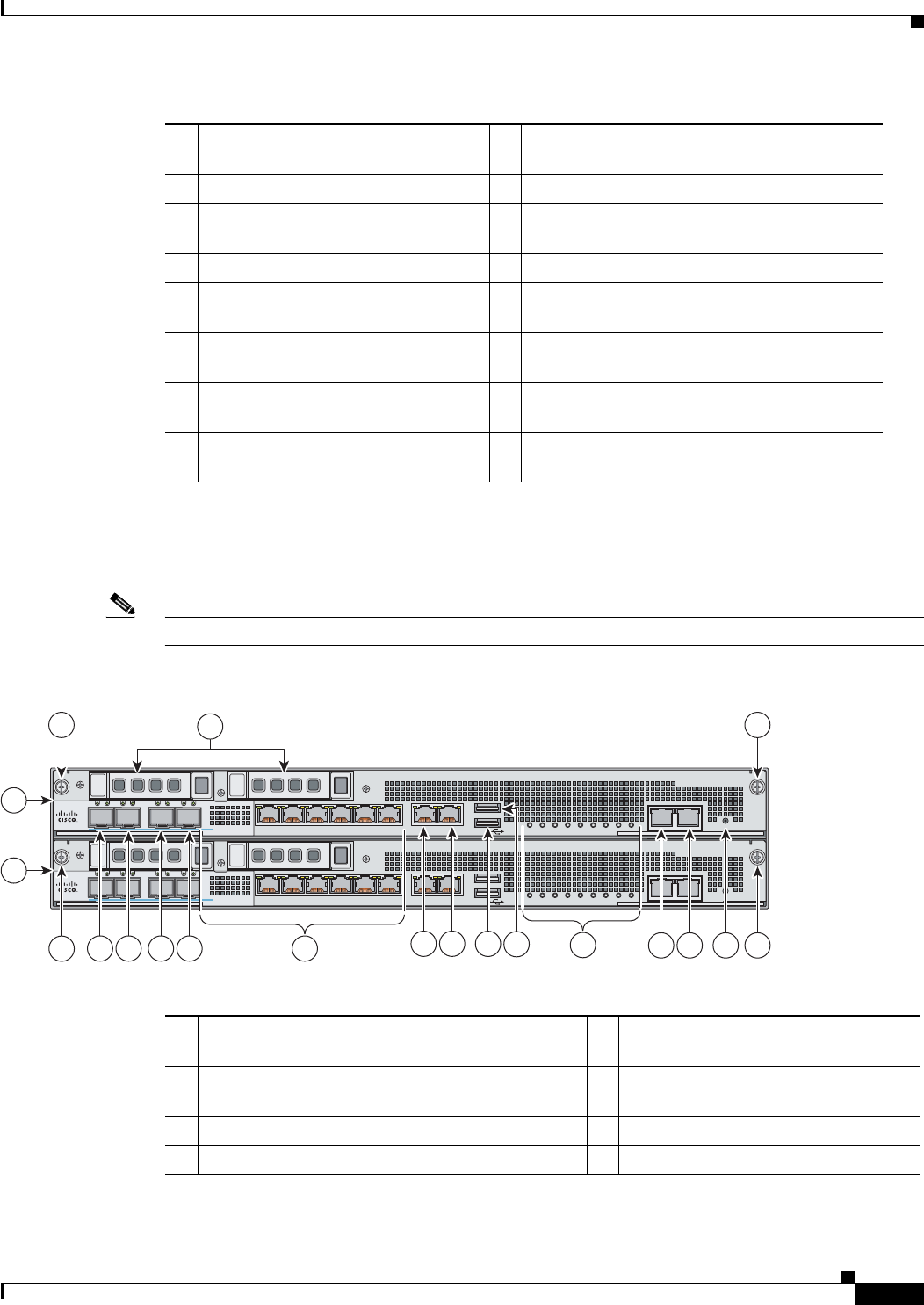
Figure 9-2 shows the front view of IPS SSP-40 and IPS SSP-60.
Note
The illustration shows IPS SSP-40, but it applies to both the -40 and the -60 models.
Figure 9-2 IPS SSP-40 Front Panel View
1 ASA 5585-X IPS SSP (Slot 1) 9 Management 0/0
(GigabitEthernet RJ45)
2 SSP (Slot 0) 10 USB port
3 SSP/ASA 5585-X IPS SSP Removal
Screws
11 USB port
4 Reserved bays for hard disk drives
1
1. Hard disk drives are not supported at this time. The hard disk drive bays are empty.
12 Front panel indicators
5 TenGigabitEthernet 0/1
(10-Gb fiber, SFP, or SFP+)
13 Auxiliary port (RJ45)
6 TenGigabitEthernet 0/0
(1-Gb fiber, SFP, or SFP+)
14 Console port (RJ45)
7 GigabitEthernet 1/0 through 1/7, from
right to left (1-Gb copper, RJ45)
15 Eject
2
2. Reserved for future use for OIR.
8 Management 0/1
(GigabitEthernet RJ45)
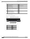
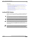
1 ASA 5585-X IPS SSP (slot 1) 10 Management 1/1
(GigabitEthernet RJ45)
2 SSP (slot 0) 11 Management 1/0
(GigabitEthernet RJ45)
3 SSP/ASA 5585-X IPS SSP removal screws 12 USB port
4 Reserved bays for hard disk drives
1
13 USB port
PWR
BOOT
ALARM
ACT
VPN
PS1
HDD1
PS0
HDD0
USB
RESET
0
7
6
1012345
MGMT
0
1
AUX CONSOLE
9
8
SFP/SFP+
Cisco ASA 5585-X IPS SSP
AUX CONSOLE
PWR
BOOT
ALARM
ACT
VPN
PS1
HDD1
PS0
HDD0
USB
RESET
0
7
6
1012345
MGMT
0
1
AUX CONSOLE
9
8
SFP/SFP+
Cisco ASA 5585-X IPS SSP
3
4
3
5
6
9
10 11
12
13
14
15 16 17
255016
3
1
2
3
7
8