


Epson Research and Development Page 9
Vancouver Design Center
Programming Notes and Examples S1D13705
Issue Date: 02/01/22 X27A-G-002-03
2.3 Frame Rate Calculation
Frame rate specifies the number of complete frame which are drawn on the display in one
second. Configuring a frame rate that is too high or too low adversely effects the quality of
the displayed image.
System configuration imposes certain non-variable limitations. For instance the width and
height of the display panel are fixed as is, typically, the input clock to the S1D13705. From
the following formula it is evident that the two variables the programmer can use to adjust
frame rate are horizontal and vertical non-display periods.
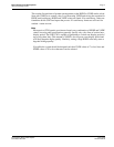
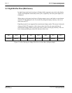
Table 2-1: S1D13705 Initialization Sequence
Register Value (hex) Notes See Also
[01] 0010 0011 (23) Select a passive, Single, Color panel with an 8-bit data width
[02] 1100 0000 (C0) Select 8-bit per pixel color depth
[03] 0000 0011 (03) Select normal power operation
[04] 0010 0111 (27) Horizontal display size = (Reg[04]+1)*8 = (39+1) * 8 = 320 pixels
[05] 1110 1111 (EF)
Vertical display size = Reg[06][05] + 1
= 0000 0000 1110 1111 + 1 = 239 +1 = 240 lines
[06] 0000 0000 (00)
[07] 0000 0000 (00) FPLINE start position (only required for TFT configuration)
[08] 0000 0000 (00)
Horizontal non-display period = (Reg[08] + 4) * 8
= 4 * 8 = 32 pixels
Frame Rate Calculation
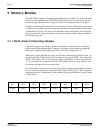
[09] 0000 0000 (00) FPFRAME start position (only required for TFT configuration)
[0A] 0000 0011 (03) Vertical non-display period = REG[0A] = 3 lines Frame Rate Calculation
[0B] 0000 0000 (00) MOD rate is only required by some monochrome panels
[0C] 0000 0000 (00)
Screen 1 Start Address - set to 0 for initialization Split Screen on page 31
[0D] 0000 0000 (00)
[0E] 0000 0000 (00)
Screen 2 Start Address - set to 0 for initialization Split Screen on page 31
[0F] 0000 0000 (00)
[10] 0000 0000 (00) Screen 1 / Screen 2 Start Address MSB - set to 0
[11] 0000 0000 (00) Memory Address offset - not virtual setup - so set to 0 Virtual Display on page 25
[12] 1111 1111 (FF)
Set the vertical size to the maximum value. Split Screen on page 31
[13] 0000 0011 (03)
[15]
Leave the LUT alone for now
Look-Up Table (LUT) on
page 15
[17]
[18] 0000 0000 (00)
GPIO control and status registers - set to “0”.
[19] 0000 0000 (00)
[1A] 0000 0000 (00) Set the scratch pad bits to “0”.
[1B] 0000 0000 (00) This is not portrait mode so set this register to “0”.
Introduction To Hardware
Rotation on page 37
[1C] 0000 0000 (00) Line Byte Count is only required for portrait mode.