


Page 12 Epson Research and Development
Vancouver Design Center
S1D13705 Interfacing to the Philips MIPS PR31500/PR31700 Processor
X27A-G-012-02 Issue Date: 01/02/13
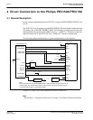
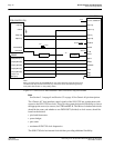
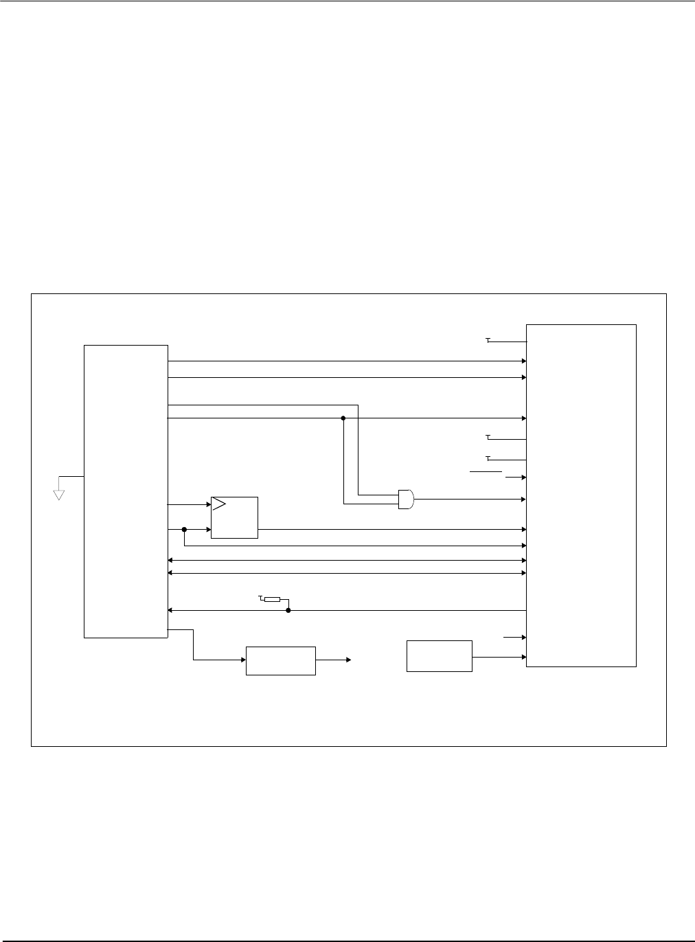
4 Direct Connection to the Philips PR31500/PR31700
4.1 General Description
In this example implementation the S1D13705 occupies the PR31500/PR31700 PC Card
slot #1.
The S1D13705 is easily interfaced to the PR31500/PR31700 with minimal additional logic.
The address bus of the PR31500/PR31700 PC Card interface is multiplexed and must be
demultiplexed using an advanced CMOS latch (e.g., 74AHC373). The direct connection
approach makes use of the S1D13705 in its “Generic #2” interface configuration.
The following diagram demonstrates a typical implementation of the interface.
Figure 4-1: S1D13705 to PR31500/PR31700 Direct Connection
Note
See Section 3.1 on page 9 and Section 3.3 on page 11 for Generic #2 pin descriptions.
WE0#
RD#
DB[7:0]
WAIT#
BCLK
S1D13705
RESET#
AB[16:13]
D[31:24]
/CARD1WAIT
A[12:0]
PR31500/PR31700
pull-up
Oscillator
WE1#
/CARD1CSL
/CARD1CSH
Latch
ALE
System RESET
/CARDIOWR
/CARDIOREAD
BS#
RD/WR#
+3.3V
+3.3V
ENDIAN
DB[15:8]
D[23:16]
AB[12:0]
V
DD
DCLKOUT
...or...
CS#
CLKI
See text
Clock divider
IO V
DD
, CORE V
DD
+3.3V
Note:
When connecting the S1D13705 RESET# pin, the system designer should be aware of all
conditions that may reset the S1D13705 (e.g. CPU reset can be asserted during wake-up
from power-down modes, or during debug states).