Page 62 Epson Research and Development
Vancouver Design Center
S1D13705 Hardware Functional Specification
X27A-A-001-10 Issue Date: 02/02/01
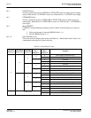
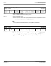
bit 7 Vertical Non-Display Status
This bit =1 during the Vertical Non-Display period.
bits 5-0 Vertical Non-Display Period
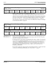
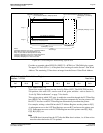
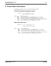
These bits specify the vertical non-display period. This register is programmed as follows:
Note
This register should be set only once, on power-up during initialization.
.
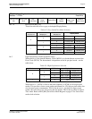
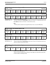
bits 5-0 MOD Rate Bits [5:0]
When the value of this register is 0, the MOD output signal toggles every FPFRAME. For
a non-zero value, the value in this register + 1 specifies the number of FPLINEs between
toggles of the MOD output signal. These bits are for passive LCD panels only.
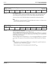
REG[0Ah] Vertical Non-Display Period
Address = 1FFEAh Read/Write
Vertical Non-
Display
Status
n/a
Vertical Non-
Display
Period Bit 5
Vertical Non-
Display
Period Bit 4
Vertical Non-
Display
Period Bit 3
Vertical Non-
Display
Period Bit 2
Vertical Non-
Display
Period Bit 1
Vertical Non-
Display
Period Bit 0
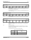
REG[0Bh] MOD Rate Register
Address = 1FFEBh Read/Write
n/a n/a
MOD Rate
Bit 5
MOD Rate
Bit 4
MOD Rate
Bit 3
MOD Rate
Bit 2
MOD Rate
Bit 1
MOD Rate
Bit 0
VerticalNonDisplayPeriod lines()REG[0Ah] bits [5:0]=


