Page 12 Epson Research and Development
Vancouver Design Center
S1D13705 S5U13705B00C Rev. 2.0 Evaluation Board User Manual
X27A-G-014-02 Issue Date: 2002/09/16
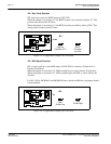
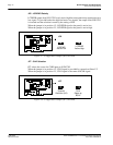
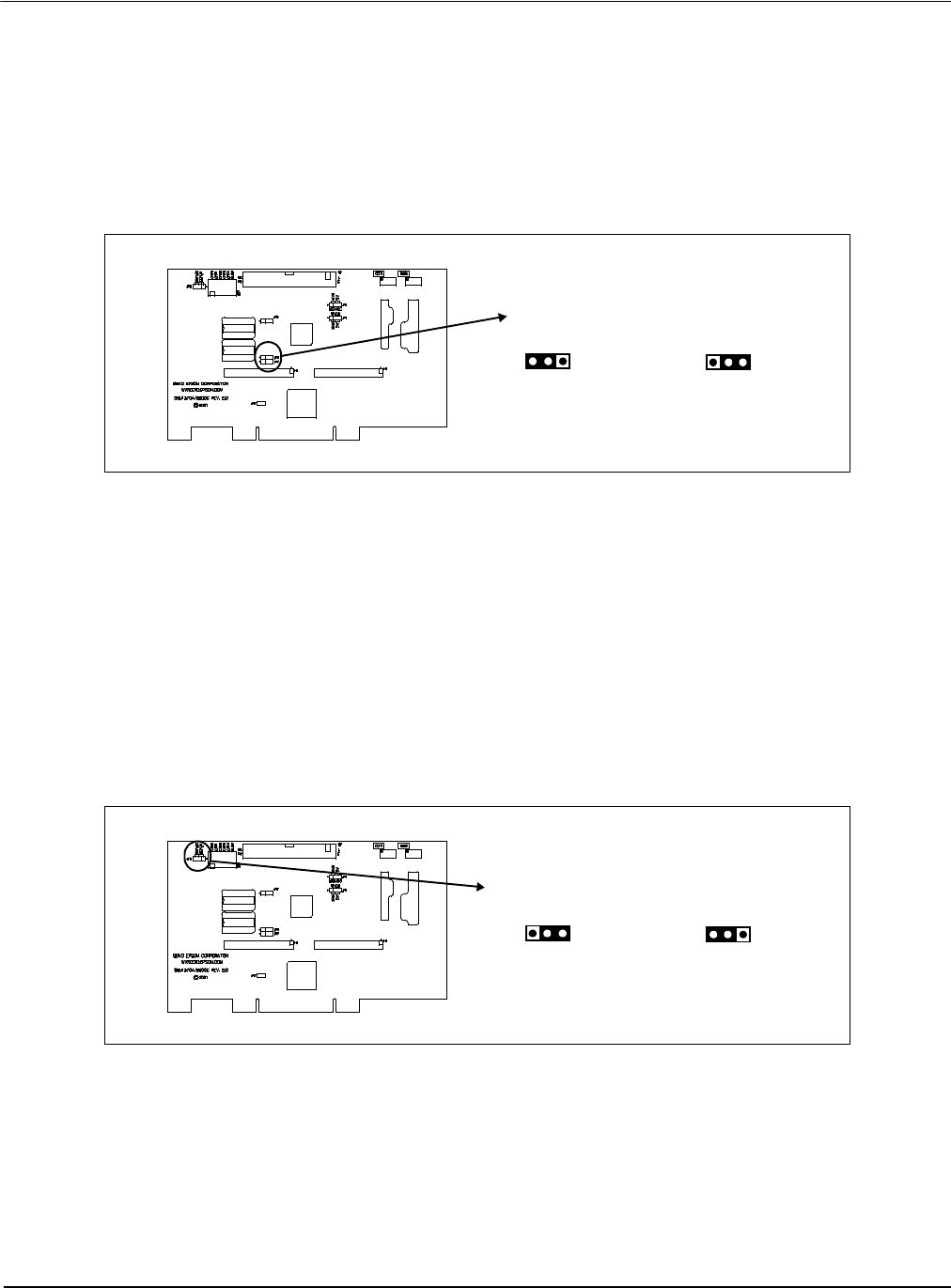
JP2 - Bus Clock Selection
JP2 selects the source for BCLK input on S1D13705.
When the jumper is in position 1-2, the BCLK source is the external oscillator U7. This
position must be used for PCI-host.
When the jumper is in position 2-3, the BCLK must be provided by the host CPU. This
setting may be used for non-PCI host.
Figure 3-3: Configuration Jumper (JP2) Location
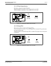
JP3 - BS# Signal Selection
JP3 is used to pull up or down BS# input of S1D13705 for selection of Generic #1 or
Generic #2 interface.
When the jumper is in position 1-2, BS# is pulled down to select Generic #1 interface.
When the jumper is in position 2-3, BS# is pulled high to IOVDD, to select Generic #2
interface.
For SH-3, SH-4, MC68K #1 and MC68K #2 buses, which use BS# line, the jumper should
not be installed.
Figure 3-4: Configuration Jumper (JP3) Location
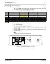
JP2
BCLK
External
Oscillator (U7)
Provided
by Host
JP3
BS#
BS#
Pulled Low
Pulled High


