Epson Research and Development Page 3
Vancouver Design Center
S5U13705B00C Rev. 1.0 ISA Bus Evaluation Board User Manual S1D13705
Issue Date: 01/02/13 X27A-G-005-03
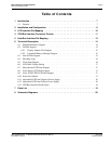
Table of Contents
1 Introduction . . . . . . . . . . . . . . . . . . . . . . . . . . . . . . . . . . . . . . . . 7
1.1 Features . . . . . . . . . . . . . . . . . . . . . . . . . . . . . . . . . .7
2 Installation and Configuration . . . . . . . . . . . . . . . . . . . . . . . . . . . . . . 8
3 LCD Interface Pin Mapping . . . . . . . . . . . . . . . . . . . . . . . . . . . . . . 10
4 CPU/Bus Interface Connector Pinouts . . . . . . . . . . . . . . . . . . . . . . . . 11
5 Host Bus Interface Pin Mapping . . . . . . . . . . . . . . . . . . . . . . . . . . . . 13
6 Technical Description . . . . . . . . . . . . . . . . . . . . . . . . . . . . . . . . . 14
6.1 Embedded Memory Support . . . . . . . . . . . . . . . . . . . . . . . . . 14
6.2 ISA Bus Support . . . . . . . . . . . . . . . . . . . . . . . . . . . . . 15
6.2.1 Display Adapter Card Support . . . . . . . . . . . . . . . . . . . . . . . . . . . . 15
6.2.2 Expanded Memory Manager Support . . . . . . . . . . . . . . . . . . . . . . . . . 15
6.3 Non-ISA Bus Support . . . . . . . . . . . . . . . . . . . . . . . . . . . 15
6.4 Decoding Logic . . . . . . . . . . . . . . . . . . . . . . . . . . . . . . 16
6.5 Clock Input Support . . . . . . . . . . . . . . . . . . . . . . . . . . . . 16
6.6 LCD Panel Voltage Setting . . . . . . . . . . . . . . . . . . . . . . . . . 17
6.7 Monochrome LCD Panel Support . . . . . . . . . . . . . . . . . . . . . . . 17
6.8 Color Passive LCD Panel Support . . . . . . . . . . . . . . . . . . . . . . 17
6.9 Color TFT/D-TFD LCD Panel Support . . . . . . . . . . . . . . . . . . . . 17
6.10 Power Save Modes . . . . . . . . . . . . . . . . . . . . . . . . . . . . 17
6.11 Adjustable LCD Panel Negative Power Supply . . . . . . . . . . . . . . . . . 18
6.12 Adjustable LCD Panel Positive Power Supply . . . . . . . . . . . . . . . . . . 18
6.13 CPU/Bus Interface Header Strips . . . . . . . . . . . . . . . . . . . . . . . 18
7 Parts List . . . . . . . . . . . . . . . . . . . . . . . . . . . . . . . . . . . . . . . . 19
8 Schematic Diagrams . . . . . . . . . . . . . . . . . . . . . . . . . . . . . . . . . . 20


