


Page 28 Epson Research and Development
Vancouver Design Center
S1D13705 Programming Notes and Examples
X27A-G-002-03 Issue Date: 02/01/22
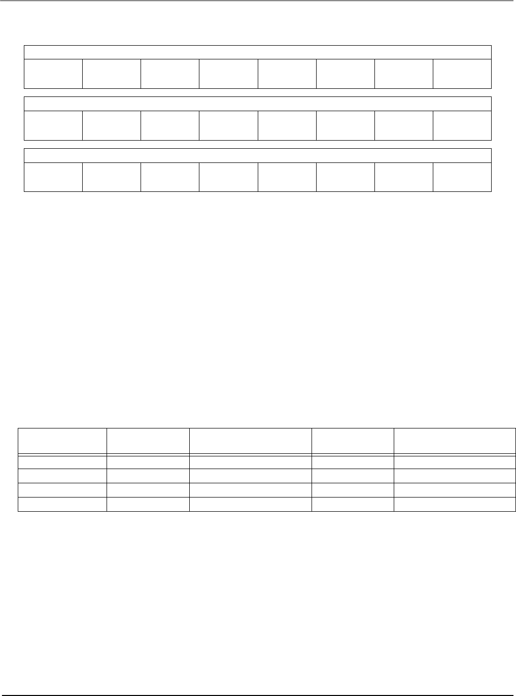
5.2.1 Registers
Screen 1 Start Address Registers
These three registers form the seventeen bit screen 1 start address. Screen 1 is displayed
starting at the top left corner of the display.
In landscape mode these registers form the word offset to the first byte in display memory
to be displayed in the upper left corner of the screen. Changing these registers by one will
shift the display image 2 to 16 pixels, depending on the current color depth.
In portrait mode these registers form the offset to the display memory byte where screen 1
will start displaying. Changing these registers in portrait mode will result in a shift of 1 to
8 pixels depending on the color depth.
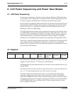
Refer to Table 5-1: “Number of Pixels Panned Using Start Address” to see the minimum
number of pixels affected by a change of one to these registers
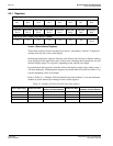
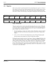
REG[0Ch] Screen 1 Display Start Address 0 (LSB)
Start Addr
Bit 7
Start Addr
Bit 6
Start Addr
Bit 5
Start Addr
Bit 4
Start Addr
Bit 3
Start Addr
Bit 2
Start Addr
Bit 1
Start Addr
Bit 0
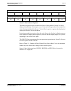
REG[0Dh] Screen 1 Display Start Address 1 (MSB)
Start Addr
Bit 15
Start Addr
Bit 14
Start Addr
Bit 13
Start Addr
Bit 12
Start Addr
Bit 11
Start Addr
Bit 10
Start Addr
Bit 9
Start Addr
Bit 8
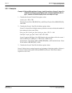
REG[10h] Screen 1 Display Start Address 2 (MSB)
n/a n/a n/a n/a n/a n/a n/a
Start Addr
Bit 16
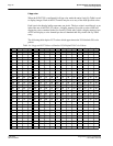
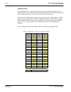
Table 5-1: Number of Pixels Panned Using Start Address
Color Depth (bpp) Pixels per Word
Landscape Mode
Number of Pixels Panned
Pixels Per Byte
Portrait Mode
Number of Pixels Panned
116 16 8 8
28 8 4 4
44 4 2 2
82 2 1 1