


Page 12 Epson Research and Development
Vancouver Design Center
S1D13705 Interfacing to the Toshiba MIPS TMPR3912 Microprocessor
X27A-G-004-02 Issue Date: 01/02/13
4 Direct Connection to the Toshiba TMPR3912
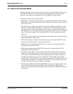
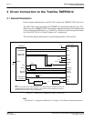
4.1 General Description
In this example implementation, the S1D13705 occupies the TMPR3912 PC Card slot #1.
The S1D13705 is easily interfaced to the TMPR3912 with minimal additional logic. The
address bus of the TMPR3912 PC Card interface is multiplexed and must be demultiplexed
using an advanced CMOS latch (e.g., 74AHC373). The direct connection approach makes
use of the S1D13705 in its “Generic Interface #2” configuration.
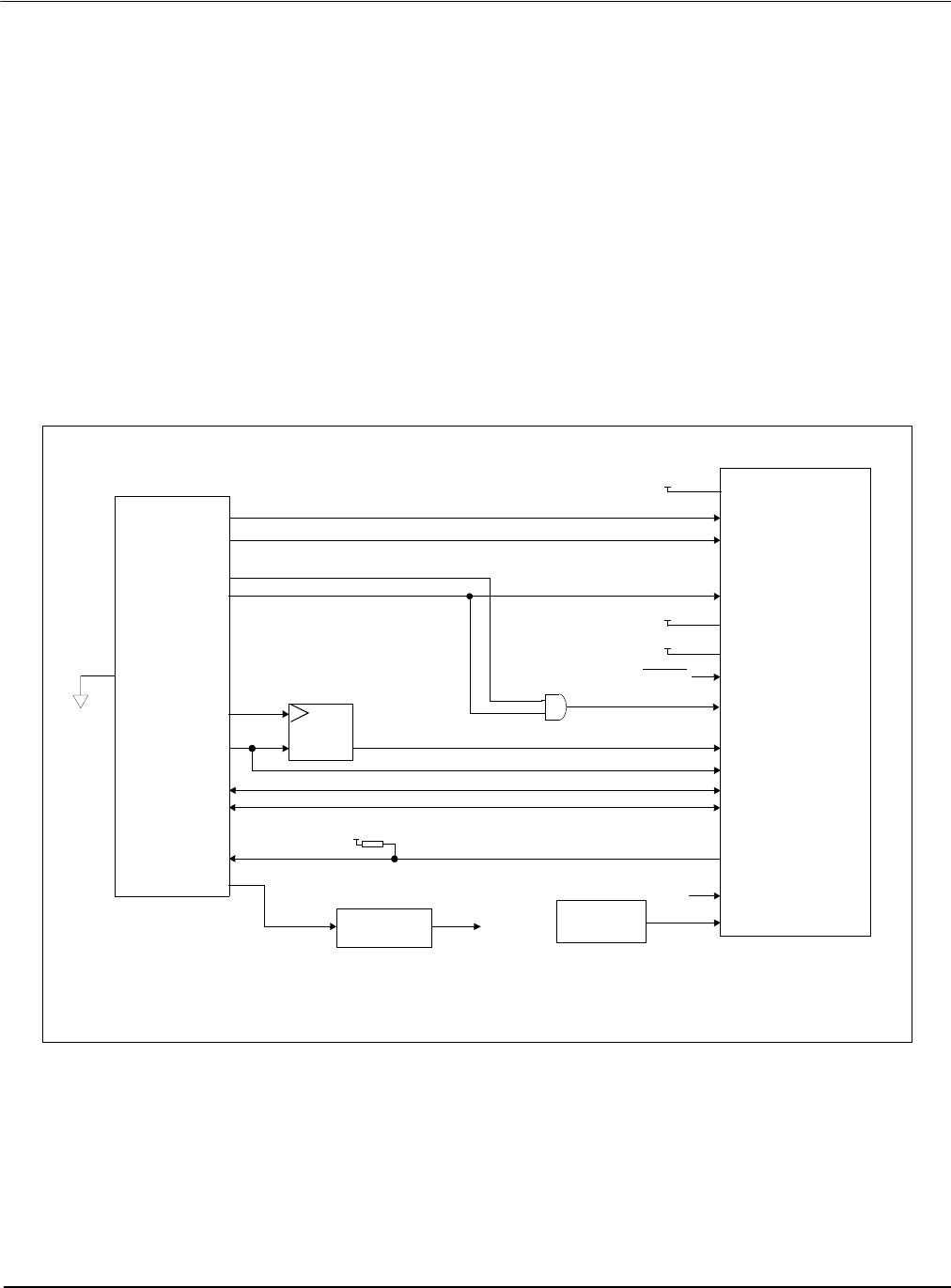
The following diagram demonstrates a typical implementation of the interface.
Figure 4-1: S1D13705 to TMPR3912 Direct Connection
Note
See Section 3.1 on page 9 and Section 3.3 on page 11 for Generic #2 pin descriptions.
WE0#
RD#
DB[7:0]
WAIT#
BCLK
S1D13705
RESET#
AB[16:13]
D[31:24]
CARD1WAIT*
A[12:0]
TMPR3912
pull-up
Oscillator
WE1#
CARD1CSL*
CARD1CSH*
Latch
ALE
System RESET
CARDIOWR*
CARDIORD*
BS#
RD/WR#
+3.3V
+3.3V
ENDIAN
DB[15:8]
D[23:16]
AB[12:0]
V
DD
DCLKOUT
...or...
CS#
CLKI
See text
Clock divider
IO V
DD
, CORE V
DD
+3.3V
Note:
When connecting the S1D13705 RESET# pin, the system designer should be aware of all
conditions that may reset the S1D13705 (e.g. CPU reset can be asserted during wake-up
from power-down modes, or during debug states).