


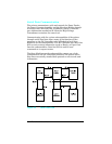

Microswitches
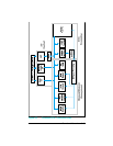
All microswitch conditions are monitored by the DC Controller
over serial data lines SLI and SLO. The State Machines on the
individual control PCAs, (for example the Paper Control PCA)
convert the switch condition to a digital logic level, and encode
that information on the data stream for the DC Controller to use.
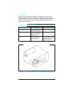
SW601 (Door Open Sensing switch) monitors the top cover. If the
top cover is open, the printing process stops and the 12
PRINTER OPEN message is displayed. SW601 disables the +24V
(B) voltage, so the printer goes through the warm-up cycle after
the cover is closed.
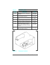
SW602 (Test Print switch) is labeled and located under the MP
tray (Tray 1) door on the right edge of the door opening. The Print
Engine Test isolates the entire printer from the Formatter PCA.
Press the Test Print switch once to start the Print Engine Test.
The Print Engine Test is a good method for finding whether print
problems are associated with the DC Controller or the Formatter
PCA.
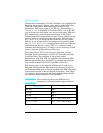
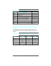
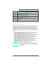
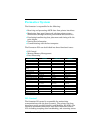
Paper tray size microswitches are activated by protrusions on
each PC tray (Tray 2). The tray size is determined by the
combination of engaged microswitches (see Table 5-3 and 5-4).
SW 603, 604, 605 (Cassette Size Switches) are for the PC tray
(Tray 2), and SW 851, 852, 853 are for the 500-sheet Lower
Cassette (Tray 3). These microswitches work together to indicate
to the DC Controller which size cassette is installed, or indicate
that the cassette is incorrectly installed. The combinations for
each cassette size are listed in Table 5-4.
5-8 Functional Overview