


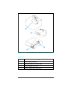

Voltage Test Points
The operating voltages of the printer can be verified by:
1
Listening for the exhaust fan. A rotating fan indicates that the
+5 VDC and +24A VDC voltages are present. (The fan runs on
+24A VDC. The +5 VDC enables the +24A VDC.)
2 Listen for the Main Motor. If the Main Motor runs, the +24B
VDC is enabled, therefore +24A VDC must be present.
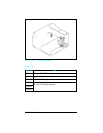
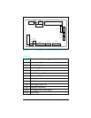
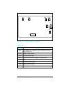
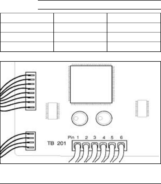
Measuring the DC Voltage Levels
The DC voltage levels can be measured directly on the DC
Controller TB 201. TB 201 connects the DC Controller with the
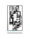
Power Supply. (See the Main Wiring Diagram, and Figure 7-16 or
7-17, the DC Controller PCA Layout in the previous section.)
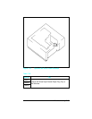
Remove the Formatter cage to access the DC Controller. The
voltages on TB201 are as follows:
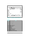
Voltage Color Pin Number
+5 VDC Brown 1, 2
+24 VDC Red 3
Ground Blue 4, 5, 6
Table 7-39
TB 201Voltages
Figure 7-21 TB 201 Voltages
Troubleshooting 7-69