


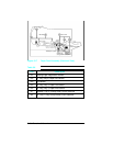


Power System
When the main power switch is turned ON, the AC Power Supply
provides AC voltage to the DC Power Supply and the fuser
assembly heat lamp. The paper path doors must be closed to
activate the AC power supply door switches before voltage is
provided to the heat lamp.
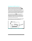
The DC Power Supply generates +5V DC, and +24V DC for use
by the Formatter PCA and the DC Controller PCA. The DC
Controller PCA distributes voltages to the remaining electrical
assemblies. Over-current protection for the DC Power Supply is
provided by a current monitoring circuit (crowbar circuit). To
reset the crowbar circuit, the printer’s power must be turned OFF
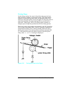
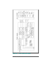
for at least ten minutes. The power system block diagram is
illustrated in Figure 5-20.
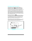
Note that both AC and DC power supplies are contained within
the Power Supply Assembly. The high voltage power supply is a
discrete assembly located on the underside of the printer.
Functional Overview 5-31