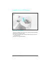
Gear Assembly Removal
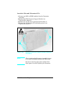
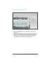
1 Remove the Top Cover, the Right Side Cover, the Fuser
Assembly, and the Formatter Assembly.
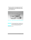
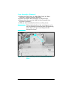
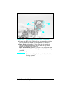
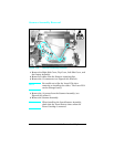
2 Remove the Main Motor Assembly (see Figure 6-30).
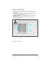
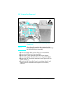
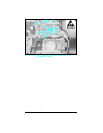
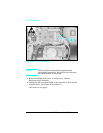
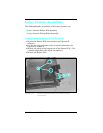
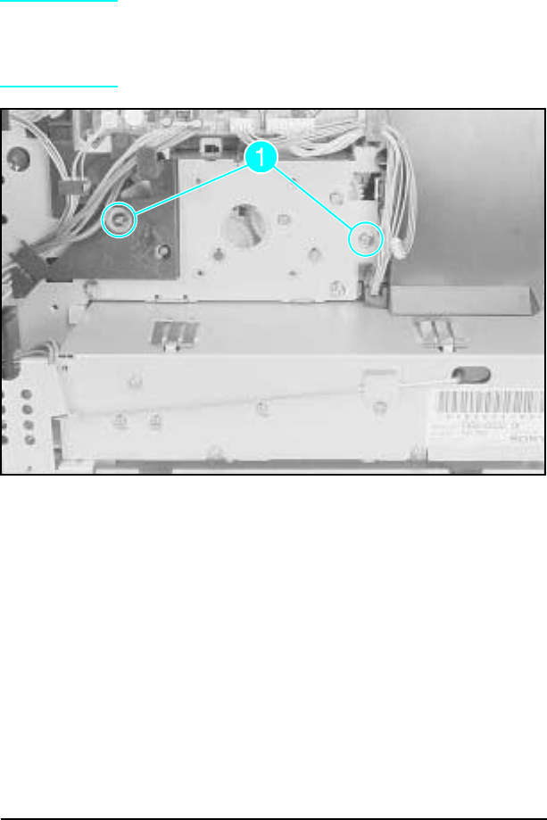
3 Remove the (2) screws that hold the Gear Assembly (see
Figure 6-31 callout 1).
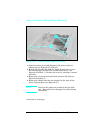
4 Slide the Gear Assembly from the rear of the printer.
Note
Before tightening down the mounting screws, be
sure the shoulder around the upper left mounting
screw hole on the gear assembly protrudes
through the frame.
Figure 1-31 Gear Assembly Screws (Located behind Main
Motor)
6-38 Removal and Replacement


