


IXF1104 Quad-Port 10/100/1000 Mbps Ethernet Media Access Controller
100 Datasheet
Document Number: 278757
Revision Number: 007
Revision Date: March 25, 2004
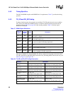
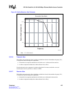
Refer to Figure 42 “MDC Low-Speed Operation Timing” on page 144 for the low frequency MDC
timing diagram.
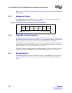
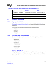
5.5.5 Management Frames
The Management Interface serializes the external register access information into the format
specified by IEEE 802.3, Section 22.2.4.5 (see Figure 21).
5.5.6 Single MDI Command Operation
The Management Data Interface is accessed through the “MDIO Single Command ($0x680)" and
the “MDIO Single Read and Write Data ($0x681)". A single management frame is sent by setting
Register 0, bit 20 to logic 1, and is automatically cleared when the frame is completed.
The Write data is first set up in Register 1, bits 15:0 for Write operation. Register 0 is initialized
with the appropriate control information (start, op code, etc.) and Register 0, bit 20 is set to logic 1.
Register 0, bit 20 is reset to logic 0 when the frame is complete.
The steps are identical for Read operation except that in Register 1, bits 15:0, the data is ignored.
The data received from the MDIO is read by the CPU interface from Register 1, bits 31:16.
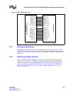
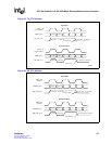
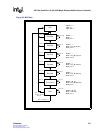
5.5.7 MDI State Machine
The MDI State Machine sequences the information sent to it by the MDIO control registers and
keeps track of the current sequence bit count, enabling or disabling the MDIO driver output (see
Figure 22.
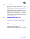
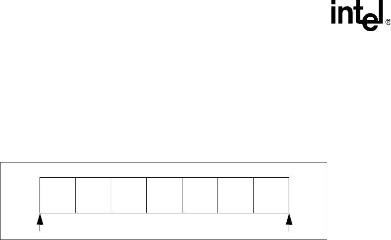
Figure 21. Management Frame Structure (Single-Frame Format)
Preamble
32 Bits
Start
2 Bits
Op Code
2 Bits
PHY Addr
5 Bits
Turnaround
2 Bits
Data
16 Bits
First Bit Transmitted Last Bit Transmitted
REG Addr
5 Bits