IXF1104 4-Port Gigabit Ethernet Media Access Controller
150 Datasheet
Document Number: 278757
Revision Number: 007
Revision Date: March 25, 2004
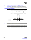
7.9 Transmit Pause Control AC Timing Specification
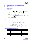
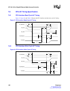
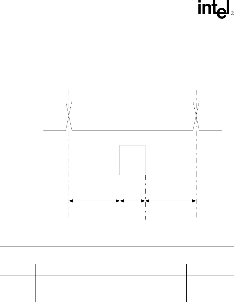
Figure 49 and Table 55 show the pause control AC timing specifications. The Pause Control
interface operates as an asynchronous interface relative to the main system clock (CLK125). There
is, however, a relationship between the TXPAUSEADD bus and the strobe signal (TXPAUSEFR).
Figure 49. Pause Control Interface Timing
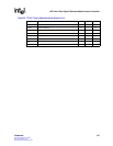
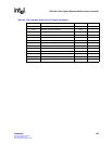
Table 55. Transmit Pause Control Interface Timing Parameters
Symbol Parameter Min Max Units
Tsu TXPAUSEADD stable prior to TXPAUSEFR High 16 – ns
Tpw TXPAUSEFR pulse width 16 – ns
Thold TXPAUSEADD stable after TXPAUSEFR High 16 – ns
TxPauseAdd[1:0]
TxPauseFr
Tsu(min) = 16 ns
Thold(min) = 16 ns
Tpw(min) = 16 ns
000 : XON packet on all ports
001 : XOFF Port0
010 : XOFF Port1
011 : XOFF Port2
100 : XOFF Port3
110-101 : Reserved
111 : XOFF on all ports
TXPAUSEADD[2:0]


