


IXF1104 4-Port Gigabit Ethernet Media Access Controller
Datasheet 189
Document Number: 278757
Revision Number: 007
Revision Date: March 25, 2004
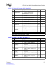
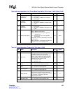
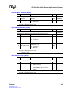
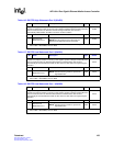
Table 107. MDIO Soft Reset ($0x506)
Bit Name Description Type
1
Default
Register Description:
Software-activated reset of the MDIO module. 0x00000000
31:1 Reserved Reserved RO 0x00000000
0 Software MDIO Reset
0 = Reset inactive
1 = Reset active
R/W 0
1. RO = Read Only, No clear on Read; R = Read, Clear on Read; W = Write only; R/W = Read/Write, No
clear; R/W/C = Read/Write, Clear on Write
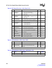
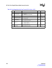
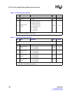
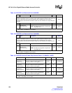
Table 108. CPU Interface ($0x508)
Bit Name Description Type
1
Default
Register Description:
CPU Interface Endian select. Allows the user to select the Endian of
the CPU interface to allow for various CPUs to be connected to the IXF1104.
0x00000000
31:25 Reserved Reserved RO 0x00
24 CPU Endian
Reserved in Little Endian
Valid in Big endian
0 = Little Endian
1 = Big Endian
R/W 0
23:1 Reserved Reserved RO 0x000000
0 CPU Endian Control
Reserved in Big Endian
Valid in Little Endian
0 = Little Endian
1 = Big Endian
R/W 0
1. RO = Read Only, No clear on Read; R = Read, Clear on Read; W = Write only; R/W = Read/Write, No
clear; R/W/C = Read/Write, Clear on Write
NOTE: Since the Endianess of the bus is unknown when writing to this register, write 0x01000001 to set the
bit and 0x0 to clear it.
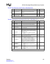
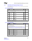
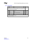
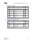
Table 109. LED Control ($0x509)
Bit Name Description Type
1
Default
Register Description:
Global selection of LED mode. 0x00000000
31:2 Reserved Reserved RO 0x00000000
1 LED Enable
0 = Disable LED Block
1 = Enable LED Block
R/W 0
0LED Control
0 = Enable LED Mode 0 for use with SGS
Thomson M5450 LED driver (Default)
1 = LED Mode 1 for use with Standard Octal Shift
register
R/W 0
1. RO = Read Only, No clear on Read; R = Read, Clear on Read; W = Write only; R/W = Read/Write, No
clear; R/W/C = Read/Write, Clear on Write