


IXF1104 Quad-Port 10/100/1000 Mbps Ethernet Media Access Controller
Datasheet 109
Document Number: 278757
Revision Number: 007
Revision Date: March 25, 2004
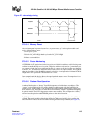
Note: MOD_DEF_INT, TX_FAULT_INT, and RX_LOS_INT are open-drain type outputs. With the
three signals on the device, the system can decide which “Optical Module Status Ports 0-3
($0x799)" bits to look at to identify the interrupt condition source port. However, this is achieved at
the expense of the three device signals.
5.7.3 I²C Module Configuration Interface
The I²C interface is supported on SFP optical modules. Details of the operation are found in the
SFP Multi-Source Agreement, which details the contents of the registers and addresses accessible
on a given Optical Module Interface supporting this interface.
The SFP MSA identifies up to 512 8-bit registers that are accessible in each optical module. The
Optical Module Interface is read-only and supports either sequential or random access to the 8-bit
parameters. The maximum clock rate of the interface is 100 kHz. All address-select signals on the
internal E²PROM are tied Low to give a device address equal to zero (00h).
Several PHY vendors may offer copper/CAT5-based SFP optical compliant modules. To program
the internal configuration registers of these modules, the IXF1104 I
2
C interface needs to provide
the capability to write data to the SFP modules.
The IXF1104 I
2
C interface is designed to allow individual writes of byte-wide data to the SFP.
The specific interface in the IXF1104 supports only a subset of the full I²C interface, and only the
features required to support the Optical Module Interfaces are implemented. This leads to the
following support features.
• Single I
2
C_CLK pin connected to all optical modules and implemented to save unnecessary
signals use.
• Four per-port I
2
C_DATA signals (I²C Data[3:0]) are required because of the optical module
requirement that all modules must be addressed as 00h.
• The interface has both read and write functionality.
• Due to the single internal optical module controller, only one optical module may be accessed
at any one time. Each access contains a single register Read. Since these register accesses will
most likely be done during power-up or discovery of a new module, these restrictions should
not affect normal operation.
• The I
2
C interface supports byte write accesses to the full address range.
5.7.3.1 I
2
C Control and Data Registers
In the IXF1104, the entire I²C interface is controlled through the following two registers:
• “I2C Control Ports 0 - 3 ($0x79B)” on page 222
• “I2C Data Ports 0 - 3 ($0x79F)” on page 222
These registers can be programmed by system software using the CPU interface.
5.7.3.2 I
2
C Read Operation
To perform a read operation using the I
2
C interface, use the following sequence:
1. Initialize the Control register by setting the following values:
a. Enable the I
2
C Controller by setting bit [25] to 0x1.