


IXF1104 4-Port Gigabit Ethernet Media Access Controller
154 Datasheet
Document Number: 278757
Revision Number: 007
Revision Date: March 25, 2004
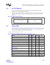
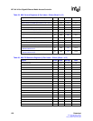
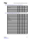
8.0 Register Set
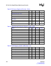
The registers shown in this section provide access for configuration, alarm monitoring, and control
of the chip. Table 59 “MAC Control Registers ($ Port Index + Offset)” on page 155 through
Table 69 “Optical Module Registers ($ 0x799 - 0x79F)” on page 161 provide register map details.
The registers are listed by ascending address in the table.
8.1 Document Structure
The following sections are structured to provide a general overview of the register map. Later
sections provide detailed descriptions of each register segment or bit.
All registers are accessed and addressed as 32-bit doublewords. When accessed using 8- or 16-bit
accesses, the CPU interface packs or unpacks the partial accesses into a 32-bit register value.
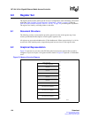
8.2 Graphical Representation
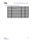
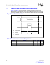
Figure 53 represents an overview of the IXF1104 global control status registers that are used to
configure or report on all ports. All register locations shown in Figure 53 represent a 32-bit double
word.
Figure 53. Memory Overview Diagram
B0744-01
Global Configuration
Reserved
Reserved
Reserved
Reserved
Reserved
Reserved
Port 3 MAC Control & Statistics
Port 2 MAC Control & Statistics
Port 1 MAC Control & Statistics
Port 0 MAC Control & Statistics
- RX Block Configuration
- TX Block Configuration
0x7FF
0x500
0x480
0x400
0x380
0x300
0x280
0x200
0x180
0x100
0x080
0x000