


IXF1104 4-Port Gigabit Ethernet Media Access Controller
Datasheet 39
Document Number: 278757
Revision Number: 007
Revision Date: March 25, 2004
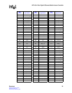
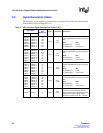
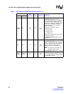
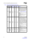
TPRTY_0 TPRTY_0
TPRTY_1
TPRTY_2
TPRTY_3
D5
G3
B9
J6
Input
3.3 V
LVTTL
Transmit Parity.
TPRTY indicates odd parity for the TDAT
bus. TPRTY is valid only when a channel
asserts either TENB or TSX. Odd parity is
the default configuration; however, even
parity can be selected (see Table 146 “SPI3
Transmit and Global Configuration
($0x700)” on page 212).
32-bit Multi-PHY mode: TPRTY_0 is the
parity bit covering all 32 bits.
4 x 8 Single-PHY mode: TPRTY_0:3 bits
correspond to the respective TDAT[3:0]_n
channels.
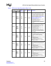
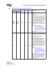
TENB_0 TENB_0
TENB_1
TENB_2
TENB_3
B7
E2
C9
J4
Input
3.3 V
LVTTL
Transmit Write Enable.
TENB_0:3 asserted causes an attached
PHY to process TDAT[n], TMOD, TSOP,
TEOP and TERR signals.
32-bit Multi-PHY mode: TENB_0 is the
enable bit for all 32 bits.
4 x 8 Single-PHY mode: TENB_0:3 bits
correspond to the respective TDAT[3:0]_n
channels and their associated control and
status signals.
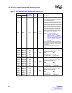
TERR_0 TERR_0
TERR_1
TERR_2
TERR_3
A8
K1
E11
J8
Input
3.3 V
LVTTL
Transmit Error.
TERR indicates that there is an error in the
current packet. TERR is valid when
simultaneously asserted with TEOP and
TENB.
32-bit Multi-PHY mode: TERR_0 is the bit
asserted for all 32 bits.
4 x 8 Single-PHY mode: Each bit of
TERR_0:3 corresponds to the respective
TDAT[3:0]_n channel.
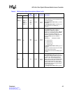
TSOP_0 TSOP_0
TSOP_1
TSOP_2
TSOP_3
C7
E3
C10
J5
Input
3.3 V
LVTTL
Transmit Start-of-Packet.
TSOP indicates the start of a packet and is
valid when asserted simultaneously with
TENB.
32-bit Multi-PHY mode: TSOP_0 is the bit
asserted for all 32 bits.
4 x 8 Single-PHY mode:
Each bit of
TSOP_0:3 corresponds to the respective
TDAT[3:0]_n channel.
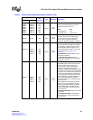
TEOP_0 TEOP_0
TEOP_1
TEOP_2
TEOP_3
A7
F3
E4
H5
Input
3.3 V
LVTTL
Transmit End-of-Packet.
TEOP indicates the end of a packet and is
valid when asserted simultaneously with
TENB.
32-bit Multi-PHY mode: TEOP_0 is the bit
asserted for all 32 bits.
4 x 8 Single-PHY mode: Each bit of
TEOP_0:3 corresponds to the respective
TDAT[3:0]_n channel.
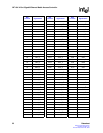
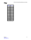
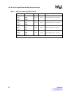
Table 3. SPI3 Interface Signal Descriptions (Sheet 2 of 8)
Signal Name
Ball
Designator
Type Standard Description
MPHY SPHY