


IXF1104 Quad-Port 10/100/1000 Mbps Ethernet Media Access Controller
Datasheet 123
Document Number: 278757
Revision Number: 007
Revision Date: March 25, 2004
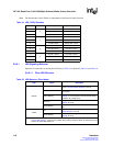
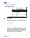
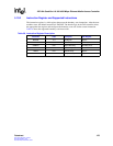
5.10.2 Instruction Register and Supported Instructions
The instruction register is a 4-bit register that enacts the boundary scan instructions. After the state
machine resets, the default instruction is IDCODE. The decode logic in the TAP controller selects
the appropriate data register and configures the boundary scan cells for the current instruction.
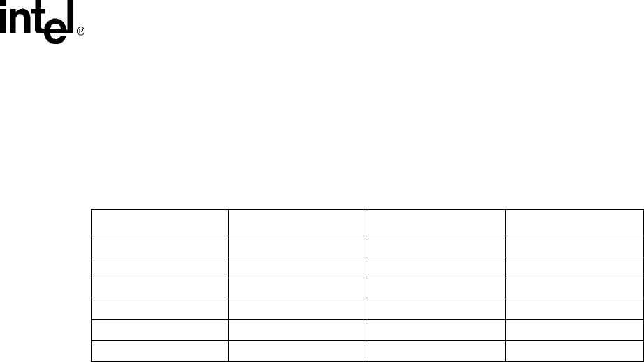
Table 38 shows the supported boundary-scan instructions.
Table 38. Instruction Register Description
Instruction Code Description Data Register
BYPASS 1111 1-bit Bypass Bypass
EXTEST 0000 External Test Boundary Scan
SAMPLE 0001 Sample Boundary Boundary Scan
IDCODE 0110 ID Code Inspection ID
HIGHZ 0101 Float Boundary Bypass
CLAMP 0111 Clamp Boundary Bypass