


IXF1104 4-Port Gigabit Ethernet Media Access Controller
Datasheet 139
Document Number: 278757
Revision Number: 007
Revision Date: March 25, 2004
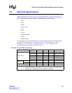
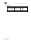
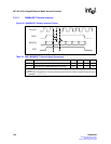
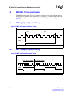
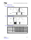
Table 47. SPI3 Transmit Interface Signal Parameters
Symbol Parameter Min Max Units
– TFCLK frequency – 133 MHz
– TFCLK duty cycle 40 60 %
TStenb TENB setup time to TFCLK 1.8 – ns
THtenb TENB hold time to TFCLK 0.5 – ns
TStdat TDAT[31:0] setup time to TFCLK 1.8 – ns
THtdat TDAT[31:0} hold time to TFCLK 0.5 – ns
TStprty TRPTY setup time to TFCLK 1.8 – ns
THtprty TPRTY hold time to TFCLK 0.5 – ns
TStsop TSOP setup time to TFCLK 1.8 – ns
THtsop TSOP hold time to TFCLK 0.5 – ns
TSteop TEOP setup time to TFCLK 1.8 – ns
THteop TEOP hold time to TFCLK 0.5 – ns
TStmod TMOD setup time to TFCLK 1.8 – ns
THtmod TMOD hold time to TFCLK 0.5 – ns
TSterr TERR setup time to TFCLK 1.8 – ns
THterr TERR hold time to TFCLK 0.5 – ns
TStsx TSX setup time to TFCLK 1.8 – ns
THtsx TSX hold time to TFCLK 0.5 – ns
TStadr TADR setup time to TFCLK 1.8 – ns
THtadr TADR hold time to TFCLK 0.5 – ns
TPdtpa TFCLK High to DTPA valid 1.5 3.7 ns
TPstpa TFCLK High to STPA valid 1.5 3.7 ns
TPptpa TFCLK High to PTPA valid 1.5 3.7 ns
NOTES:Transmit I/O Timing:
1. When a setup time is specified between an input and a clock, the setup time is the time in nanoseconds
from the 1.4 V point of the input to the 1.4-volt point of the clock.
2. When a hold time is specified between an input and clock, the hold time is the time in nanoseconds from
the 1.4 V point of the clock to the 1.4-volt point of the input.
3. Output propagation delay time is the time in nanoseconds from the 1.4 V point of the reference signal to the
1.4 V point of the output.