IXF1104 Quad-Port 10/100/1000 Mbps Ethernet Media Access Controller
122 Datasheet
Document Number: 278757
Revision Number: 007
Revision Date: March 25, 2004
5.10 TAP Interface (JTAG)
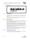
The IXF1104 includes an IEEE 1149.1 compliant Test Access Port (TAP) interface used during
boundary scan testing. The interface consists of the following five signals:
• TDI – Serial Data Input
• TMS – Test Mode Select
• TCLK – TAP Clock
• TRST_L – Active Low asynchronous reset for the TAP
• TDO – Serial Data Output
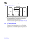
TDI and TMS require external pull-up resistors to float the signals High per the IEEE 1149.1
specification. Pull-ups are recommended on TCK and TDO. For normal operation, TRST_L can be
pulled Low, permanently disabling the JTAG interface. If the JTAG interface is used, the TAP
controller must be reset as described in Section 5.10.1, “TAP State Machine” on page 122 and
returned to a logic High.
5.10.1 TAP State Machine
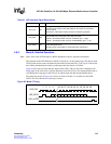
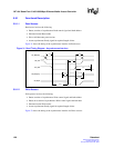
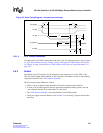
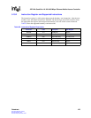
The TAP signals drive a TAP controller, which implements the 16-state state machine specified by
the IEEE 1149.1 specification. Following power-up, the TAP controller must be reset by one of
following two mechanisms:
• Asynchronous reset
• Synchronous reset
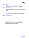
Asynchronous reset is achieved by pulsing or holding TRST_L Low. Synchronous reset is
achieved by clocking TCLK with five clock pulses while TMS is held or floats High. This ensures
that the boundary scan cells do not block the pin to core connections in the IXF1104.
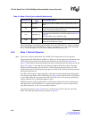
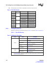
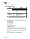
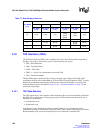
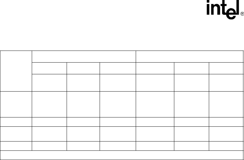
Table 37. Byte Swapper Behavior
UPX_BADD
[1:0]
Little Endian Big Endian
32-bit 16-bit 8-bit
1
32-bit 16-bit 8-bit
1
UPX_DATA_
[31:0]
UPX_DATA_
[15:0]
UPX_DATA
[7:0]
UPX_DATA
[31:0]
UPX_DATA
[15:0]
UPX_DATA
[7:0]
00 [31:0] [15:0] [7:0]
[7:0]
[15:8]
[23:16
[31:24]
[7:0]
[15:8]
[7:0]
01 – – [15:8] – – [15:8]
10 – [31:16] [23:16] –
[23:16]
[31:24]
[23:16]
11 – – [31:24] – – [31:24]
1. In 8-bit mode, data is output in Little Endian format regardless of the IXF1104 Endian setting.


