


IXF1104 4-Port Gigabit Ethernet Media Access Controller
Datasheet 47
Document Number: 278757
Revision Number: 007
Revision Date: March 25, 2004
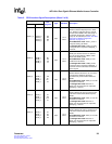
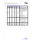
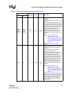
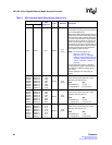
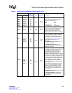
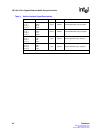
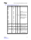
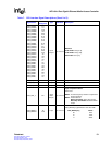
Table 5. GMII Interface Signal Descriptions (Sheet 1 of 2)
Signal Name Ball Designator Type Standard Description
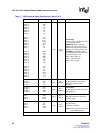
TXD7_0
TXD6_0
TXD5_0
TXD4_0
TXD3_0
TXD2_0
TXD1_0
TXD0_0
TXD7_1
TXD6_1
TXD5_1
TXD4_1
TXD3_1
TXD2_1
TXD1_1
TXD0_1
TXD7_2
TXD6_2
TXD5_2
TXD4_2
TXD3_2
TXD2_2
TXD1_2
TXD0_2
TXD7_3
TXD6_3
TXD5_3
TXD4_3
TXD3_3
TXD2_3
TXD1_3
TXD0_3
Y4
AB4
AC3
AB3
AA3
Y3
Y2
Y1
AC9
AD8
AB8
AA7
AD9
AB9
AB7
AC7
AA18
AA20
AB19
AD16
AB23
AB22
AB21
AB20
W14
AA16
Y15
AA14
V17
V16
V15
V14
Output
2.5 V
CMOS
Transmit Data.
Each bus carries eight data bits [7:0] of
the transmitted data stream to the PHY
device.
RGMII Mode: When a port is
configured in copper mode and the
RGMII interface is selected, only bits
TXD[3:0]_n are used. The data is
transmitted on both edges of TXC_0:3.
Fiber Mode: The following signals
have multiplexed functions when a port
is configured in fiber mode:
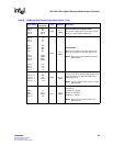
TXD4_n: TX_DISABLE_0:3
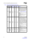
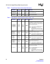
TX_EN_0
TX_EN_1
TX_EN_2
TX_EN_3
AB2
Y8
AC22
V12
Output
2.5 V
CMOS
Transmit Enable.
TX_EN indicates that valid data is
being driven on the corresponding
Transmit Data: TXD_0, TXD_1, TXD_2,
and TXD_3.
TX_ER_0
TX_ER_1
TX_ER_2
TX_ER_3
W1
AD6
AD17
AB13
Output
2.5 V
CMOS
Transmit Error:
TX_ER indicates a transmit error in the
corresponding Transmit Data: TXD_0,
TXD_1, TXD_2, and TXD_3.
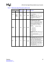
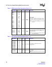
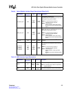
TXC_0
TXC_1
TXC_2
TXC_3
AA1
AD7
AC20
AB14
Output
2.5 V
CMOS
Source Synchronous Transmit
Clock.
This clock is supplied synchronous to
the transmit data bus in either RGMII or
GMII mode.
NOTE: Shares the same balls as RXC
on the RGMII interface.
NOTE: Refer to the RGMII interface for shared data and clock signals.