


IXF1104 4-Port Gigabit Ethernet Media Access Controller
222 Datasheet
Document Number: 278757
Revision Number: 007
Revision Date: March 25, 2004
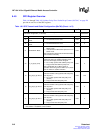
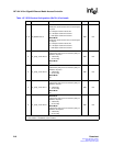
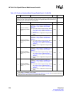
Table 155. I
2
C Control Ports 0 - 3 ($0x79B)
Bit Name Description Type
1
Default
Register Description:
This register controls and monitors the interface to the optical modules
when used in fiber mode.
0x00000000
31:28 Reserved Reserved RO 0x0
27 wp_err
An attempt to write to the protected E
2
PROM has
occurred.
R0
26 no_ack_err
This bit is set to 1 when a write and subsequent
read from an Optical Module Interface has failed.
This signal should be used to validate the data
being read. Data is only valid if this bit is equal to
zero.
R0
25 I
2
C_enable Enable the I
2
C block. R/W 0
24 I
2
C_start Start the I
2
C transfer. R/W 0
23 Reserved Reserved RO 0
22 write_complete Bit is asserted when write access is complete. R 0
21 Reserved Reserved RO 0
20 Read_complete Bit asserted when read access is complete. R 0
19:18 Reserved Reserved RO 0
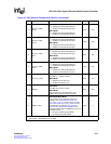
17:16 Port Select
Selects the port for which the I
2
C transaction is
targeted. Valid range is 0 to 3.
R/W 00
15 Read/Write
0 = Write transaction
1 = Read transaction
R/W 0
14:11 Device ID Most-significant four bits of device address field. R/W 0x0
10:0 Register Address
Bits 10:8 select the least-significant three bits of
the device address field
Bits 7:0 select the word/register address
R/W 0x000
1. RO = Read Only, No clear on Read; R = Read, Clear on Read; W = Write only; R/W = Read/Write, No
clear; R/W/C = Read/Write, Clear on Write
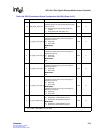
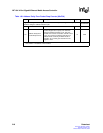
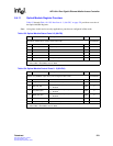
Table 156. I
2
C Data Ports 0 - 3 ($0x79F)
Bit Name Description Type
1
Default
Register Description:
These registers hold data bytes that are read and written using the I
2
C
interface to Optical Module Interfaces connected to each port of the IXF1104 4-Port Gigabit
Ethernet Media Access Controller.
0x00000000
31:24 Reserved Reserved RO 0x00
23:16 Write Data
Bit 23=MSB, Bit 16 = LSB
Data to be written to the Optical Module Interface.
R/W 0X00
15:8 Reserved Reserved RO 0x00
7:0 Read Data
Bit 7 = MSB, Bit 0 = LSB
Data read from the Optical Module Interface.
R/W 0X00
1. RO = Read Only, No clear on Read; R = Read, Clear on Read; W = Write only; R/W = Read/Write, No
clear; R/W/C = Read/Write, Clear on Write