


IXF1104 Quad-Port 10/100/1000 Mbps Ethernet Media Access Controller
102 Datasheet
Document Number: 278757
Revision Number: 007
Revision Date: March 25, 2004
5.5.8 Autoscan Operation
The autoscan function allows the 32 registers in each external PHY (up to four) to be stored
internally in the IXF1104. Autoscan is enabled by setting bit 1 of the MDI Control register. When
enabled, autoscan runs continuously, reading each PHY register. When a PHY register access is
instigated through the CPU interface, the current autoscan register Read is completed before the
CPU register access starts. Upon completion of the CPU-induced access, the autoscan functionality
restarts from the last autoscan register access.
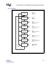
The“Autoscan PHY Address Enable ($0x682)" determines which PHY addresses are being
occupied for each IXF1104 port. The least significant bit (LSB) that is set in the register is Port 0,
the next significant bit that is set is assumed to be port 1, and so on. If more than four bits are set,
the bits beyond the fourth bit are ignored. If less than four bits are set, the round-robin process
returns to the port identified by the LSB being set.
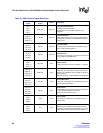
5.6 SerDes Interface
The IXF1104 integrates four integrated Serializer/Deserializer (SerDes) devices that allow direct
connection to optical modules and remove the requirement for external SerDes devices. This
increases integration, which reduces the size of the PCB area required to implement this function,
reduces total power, reduces silicon and manufacturing costs, and improves reliability. Each
SerDes interface is identical and fully compliant with the relevant IEEE 802.3 Specifications,
including auto-negotiation. Each port is also compliant with and supports the requirements of the
Small Form Factor Pluggable (SFP) Multi-Source Agreement (MSA), see Section 5.7, “Optical
Module Interface” on page 106.
The following sections describe the operations supported by each interface, the configurable
options, and the register bits that control these options. A full list of the register addresses and full
bit definitions are found in the register maps (Table 59 through Table 69).
5.6.1 Features
The SerDes cores are designed to operate in point-to-point data transmission applications. While
the core can be used across various media types, such as PCB or backplanes, it is configured
specifically for use in 1000BASE-X Ethernet fiber applications in the IXF1104. The following
features are supported.
• 10-bit data path, which connects to the output/input of the 8B/10B encoder/decoder PCS that
resides in the MAC controller
• Data frequency of 1.25 GHz
• Low power: <200 mW per SerDes port
• Asynchronous clock data recovery
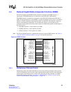
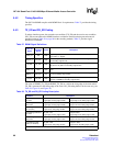
5.6.2 Functional Description
The SerDes transmit interface sends serialized data at 1.25 GHz. The interface is differential with
two signals for transmit operation. The transmit interface is designed to operate in a 100 Ω
differential environment and all the terminations are included on the device. The outputs are high-