


IXF1104 Quad-Port 10/100/1000 Mbps Ethernet Media Access Controller
90 Datasheet
Document Number: 278757
Revision Number: 007
Revision Date: March 25, 2004
5.2.2.8.2 Parity
The IXF1104 can be odd or even (the IXF1104 defaults to odd) when calculating parity on the data
bus. This can be changed to accommodate even parity if desired, and can be set for transmit and
receive ports independently. The RX and TX parity sense bits have a direct relationship to the port
parity in SPHY mode.
The per port RX parity is set in the “SPI3 Receive Configuration ($0x701)" and the per port TX
Parity is set in the “SPI3 Transmit and Global Configuration ($0x700)".
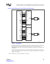
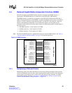
5.2.2.9 SPI3 Flow Control
The SPI3 packet interface supports transmit and receive data transfers at clock rates independent of
the line bit rate. As a result, the IXF1104 supports packet rate decoupling using internal FIFOs.
These FIFOs are 10 KB per port in the transmit direction (egress from the IXF1104 to the line
interfaces) and 32 KB per port in the receive direction (ingress to the IXF1104 from the line
interfaces).
Control signals are provided to the network processor and the IXF1104 to allow either one to
exercise flow control. Since the bus interface is point-to-point, the receive interface of the IXF1104
pushes data to the link-layer device. For the transmit interface, the packet available status
granularity is byte-based.
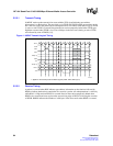
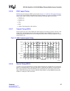
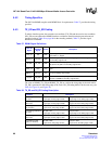
5.2.2.9.1 RX SPI3 Flow Control
In the receive direction, when the IXF1104 has stored an end-of-packet (a complete small packet or
the end of a larger packet) or some predefined number of bytes in its receive FIFO, it sends the in-
band address followed by FIFO data to the link-layer device (in MPHY mode). The data on the
interface bus is marked with the valid signal (RVAL) asserted. The network processor device can
pause the data flow by de-asserting the Receive Read Enable (RENB) signal.
RENB_0:3
RENB_0:3 controls the flow of data from the IXF1104 RX FIFOs. In SPHY mode, there is a
dedicated RENB for each port. In MPHY mode, RENB_0 is used as the global signal covering all
ports. When RENB is sampled Low, the network processor can accept data. A read is performed
from the RX FIFO and the RDAT, RPRTY, RMOD[1:0], RSOP, REOP, RERR, RSX, and RVAL
signals are updated on the following rising edge of RFCLK.
RENB can be asserted High by the Network Processor at any time if it is unable to accept any more
data. When the RENB is sampled High by the IXF1104, a read of the RX FIFO is not performed,
and the RDAT, RPRTY, RMOD[1:0], RSOP, REOP, RERR, RSX and RVAL signals remain
unchanged on the following rising edge of RFCLK.
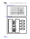
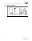
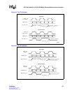
5.2.2.9.2 TX SPI3 Flow Control
In the transmit direction, when the IXF1104 has space for some predefined number of bytes in its
transmit FIFO, it informs the Network Processor device by asserting one of the Transmit Packet
Available (TPA) signals. The Network Processor device writes the in-band address followed by
packet data to the IXF1104 using an enable signal (TENB). The network processor device monitors
the TPA signals for a High-to-Low transition, which indicates that the transmit FIFO is almost full
(the number of bytes left in the FIFO is user-selectable by setting the “TX FIFO High Watermark
Ports 0 - 3 ($0x600 – 0x603)", and suspends data transfer to avoid an overflow. The Network
Processor device can pause the data flow by de-asserting the enable signal (TENB).