


IXF1104 4-Port Gigabit Ethernet Media Access Controller
58 Datasheet
Document Number: 278757
Revision Number: 007
Revision Date: March 25, 2004
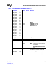
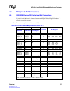
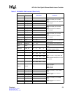
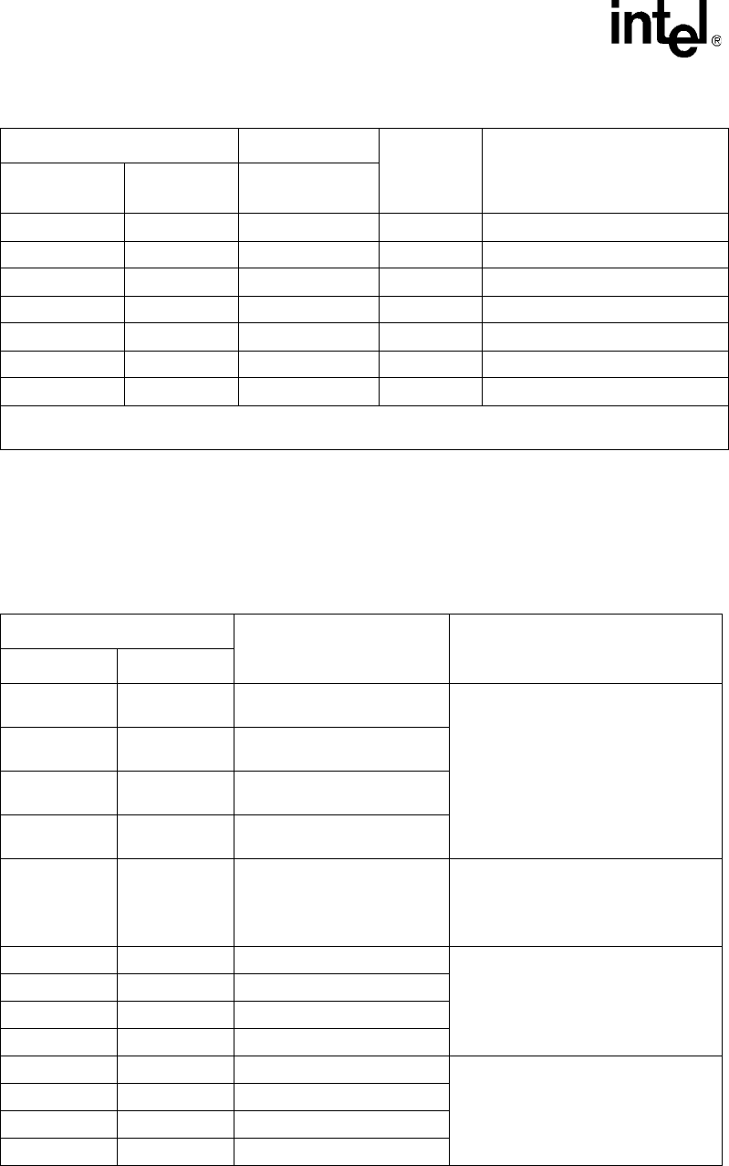
4.5.2 SPI3 MPHY/SPHY Ball Connections
Table 17 lists the balls used for the SPI3 Interface and provides a guide to connect these balls in
MPHY and SPHY mode.
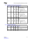
NC NC TX_FAULT_INT
2
NC P23
NC NC RX_LOS_INT
2
NC P19
NC NC MOD_DEF_INT
2
NC N22
MDC MDC NC NC W24
MDIO
2
MDIO
2
NC NC V21
NC NC I
2
C_CLK NC L23
NC NC I
2
C_DATA_0:3
2
NC L24 M24 N24 P24
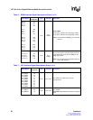
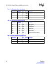
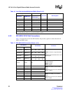
Table 16. Line Side Interface Multiplexed Balls (Sheet 2 of 2)
Copper Mode Fiber Mode
Unused Port Ball Designator
GMII Signal RGMII Signal
Optical Module/
SerDes Signal
1. An external pull-up resistor is required with most optical modules.
2. An open drain I/O, external 4.7 k Ω pull-up resistor is required.
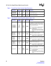
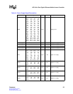
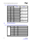
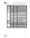
Table 17. SPI3 MPHY/SPHY Interface (Sheet 1 of 3)
SPI3 Signals
Ball Number Comments
MPHY SPHY
TDAT[31:24] TDAT[7:0]_3
F7
G7
F5
G6
G9
G5
G8
G4
MPHY: Consists of a single 32-bit data
bus
SPHY: Separate 8-bit data bus for each
Ethernet port
TDAT[23:16] TDAT[7:0]_2
C8
E8
F9
E7
E10
E6
E9
E5
TDAT[15:8] TDAT[7:0]_1
H3
H1
J3
G2
J2
G1
J1
F1
TDAT[7:0] TDAT[7:0]_0
C6
D1
B5
C3
C5
C2
C4
B3
TFCLK TFCLK D7
To achieve maximum bandwidth, set
TFCLK as follows:
MPHY: 133 Mhz
SPHY: 125 Mhz.
TPRTY_0 TPRTY_0 D5
MPHY: Use TPRTY_0 as the TPRTY
signal.
SPHY: Each port has its own dedicated
TPRTY_n signal.
GND TPRTY_1 G3
GND TPRTY_2 B9
GND TPRTY_3 J6
TENB_0 TENB_0 B7
MPHY: Use TENB_0 as the TENB
signal.
SPHY: Each port has its own dedicated
TENB_n signal.
VDD2 TENB_1 E2
VDD2 TENB_2 C9
VDD2 TENB_3 J4