


IXF1104 4-Port Gigabit Ethernet Media Access Controller
44 Datasheet
Document Number: 278757
Revision Number: 007
Revision Date: March 25, 2004
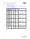
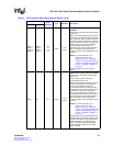
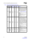
RERR_0 RERR_0
RERR_1
RERR_2
RERR_3
A16
G17
D20
H20
Output
3.3 V
LVTTL
Receive Error.
RERR indicates that the current packet is in
error. RERR is only asserted when REOP is
asserted. Conditions that can cause RERR
to be set include FIFO overflow, CRC error,
code error, and runt or giant packets.
NOTE: RERR can only be set for these
conditions if bit 0 in the “SPI3
Receive Configuration ($0x701)” is
set to 1.
RERR is considered valid only when RVAL
is asserted.
32-bit Multi-PHY mode: RERR_0 covers
all 32 bits.
4 x 8 Single-PHY mode: The RERR_0:3
bits correspond to the RDAT[7:0]_n
channels.
(n = 0, 1, 2, or 3)
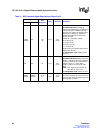
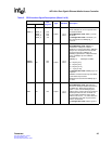
RVAL_0 RVAL_0
RVAL_1
RVAL_2
RVAL_3
C15
B18
E19
F22
Output
3.3 V
LVTTL
Receive Data Valid.
RVAL indicates the validity of the receive
data signals. RVAL is Low between
transfers and assertion of RSX. It is also
Low when the IXF1104 pauses a transfer
due to an empty receive FIFO. When a
transfer is paused by holding RENB High,
RVAL holds its value unchanged, although
no new data is present on RDAT[31:0] until
the transfer resumes. When RVAL is High,
the RDAT[31:0], RMOD[1:0], RSOP, REOP,
and RERR signals are valid. When RVAL is
Low, the RDAT[31:0], RMOD[1:0], RSOP,
REOP, and RERR signals are invalid and
must be disregarded.
The RSX signal is valid only when RVAL is
Low.
32-bit Multi-PHY mode: RVAL_0 covers all
receive bits.
4 x 8 Single-PHY mode: The RVAL_0:3
bits correspond to the per-port data and
control signals.
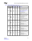
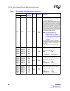
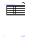
RSOP_0 RSOP_0
RSOP_1
RSOP_2
RSOP_3
B16
C18
E23
J18
Output
3.3 V
LVTTL
Receive Start of Packet.
RSOP indicates the start of a packet when
asserted with RVAL.
32-bit Multi-PHY mode: RSOP_0 covers
all 32 bits.
4 x 8 Single-PHY mode: The RSOP_0:3
bits correspond to the RDAT[7:0]_n
channels.
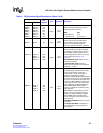
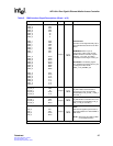
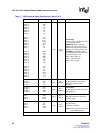
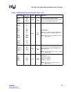
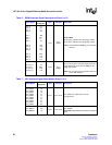
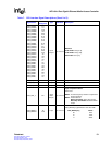
Table 3. SPI3 Interface Signal Descriptions (Sheet 7 of 8)
Signal Name
Ball
Designator
Type Standard Description
MPHY SPHY