


IXF1104 4-Port Gigabit Ethernet Media Access Controller
60 Datasheet
Document Number: 278757
Revision Number: 007
Revision Date: March 25, 2004
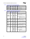
4.6 Ball State During Reset
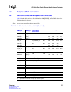
RERR_0 RERR_0 A16
MPHY: Use RERR_0 as the RERR
signal.
SPHY: Each port has a dedicated
RERR_n signal
NC RERR_1 G17
NC RERR_2 D20
NC RERR_3 H20
RVAL_0 RVAL_0 C15
MPHY: Use RVAL_0 as the RVAL
signal.
SPHY: Each port has a dedicated
RVAL_n signal.
NC RVAL_1 B18
NC RVAL_2 E19
NC RVAL_3 F22
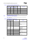
RSOP_0 RSOP_0 B16
MPHY: Use TSOP_0 as the TSOP
signal.
SPHY: Each port has a dedicated
TSOP_n signal.
NC RSOP_1 C18
NC RSOP_2 E23
NC RSOP_3 J18
REOP_0 REOP_0 C16
MPHY: Use TEOP_0 as the TEOP
signal.
SPHY: Each port has a dedicated
TEOP_n signal.
NC REOP_1 D18
NC REOP_2 C23
NC REOP_3 J19
RMOD[1:0] NC G13 G14
RSX and RMOD[1:0] are applicable
only in MPHY mode.
RSX NC E13
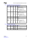
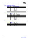
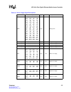
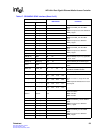
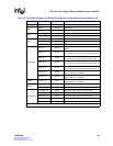
Table 18. Definition of Output and Bi-directional Balls During Hardware Reset (Sheet 1 of 2)
Interface Ball Name Ball Reset State Comment
SPI3
DTPA_0:3 0x0 –
STPA 0x0 –
PTPA 0x0 –
RDAT[31:0] 0x00000000 –
RVAL_0:3 0x0 –
RERR_0:3 0x0 –
RPRTY_0:3 0x0 –
RMOD[1:0] 0x0 –
RSX 0x0 –
RSOP_0:3 0x0 –
REOP_0:3 0x0 –
NOTE: Z = High impedance.
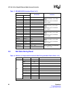
Table 17. SPI3 MPHY/SPHY Interface (Sheet 3 of 3)
SPI3 Signals
Ball Number Comments
MPHY SPHY