


IXF1104 4-Port Gigabit Ethernet Media Access Controller
Datasheet 61
Document Number: 278757
Revision Number: 007
Revision Date: March 25, 2004
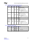
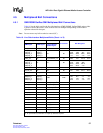
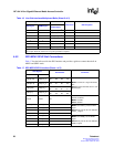
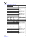
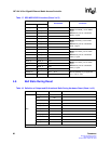
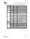
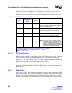
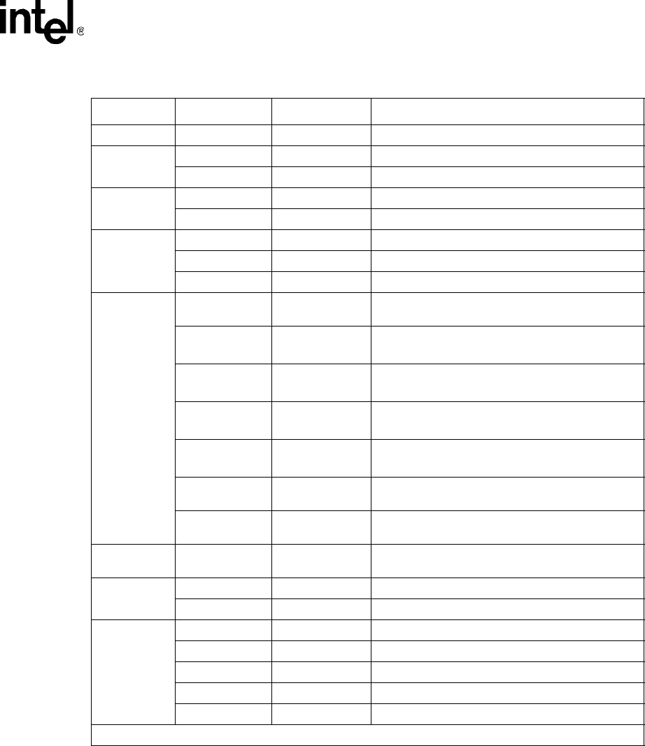
JTAG TDO 0x0 –
MDIO
MDIO High Z Bi-directional
MDC 0x0 –
CPU
UPX_DATA[31:0] High Z Bi-directional
UPX_RDY_L 0X1 Open-drain output, requires an external pull-up
LED
LED_CLK 0x0 –
LED_DATA 0x0 –
LED_LATCH 0x0 –
GMII/RGMII
TXC_0:3 High Z
Fiber mode is the default. Copper interfaces are
disabled.
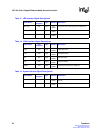
TXD[7:0]_0 High Z
Fiber mode is the default.
Bit 4 is driven by the optical module as MOD_DEF_0.
TXD[7:0]_1 High Z
Fiber mode is the default.
Bit 4 is driven by the optical module as MOD_DEF_1.
TXD[7:0]_2 High Z
Fiber mode is the default.
Bit 4 is driven by the optical module as MOD_DEF_2.
TXD[7:0]_3 High Z
Fiber mode is the default.
Bit 4 is driven by the optical module as MOD_DEF_3.
TX_EN_0:3 High Z
Fiber mode is the default.
Copper interfaces are disabled.
TX_ER_0:3 High Z
Fiber mode is the default.
Copper interfaces are disabled.
RGMII TX_CTL_0:3 High Z
Fiber mode is the default.
Copper interfaces are disabled.
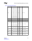
SerDes
TX_P_0:3 0x0 –
TX_N_0:3 0x0 –
Optical Module
TX_FAULT_INT High Z Open-drain output, requires external pull-up.
RX_LOS_INT High Z Open-drain output, requires external pull-up.
MOD_DEF_INT High Z Open-drain output, requires external pull-up.
I
2
C_CLK 0x1 –
I
2
C_DATA_0:3 0xF Open-drain output, requires external pull-up.
Table 18. Definition of Output and Bi-directional Balls During Hardware Reset (Sheet 2 of 2)
Interface Ball Name Ball Reset State Comment
NOTE: Z = High impedance.