


IXF1104 Quad-Port 10/100/1000 Mbps Ethernet Media Access Controller
126 Datasheet
Document Number: 278757
Revision Number: 007
Revision Date: March 25, 2004
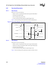
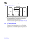
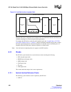
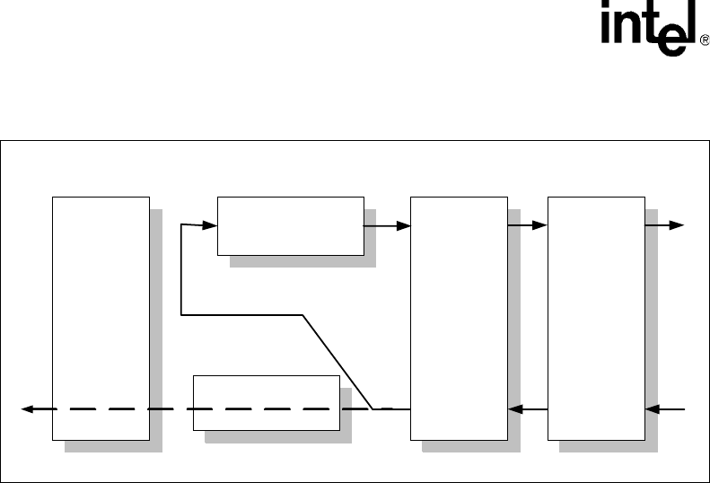
When the IXF1104 is configured in this loopback mode, all of the MAC functions and features are
available, including flow control and pause-packet generation.
To configure the IXF1104 to use the line-side loopback mode, the “Loop RX Data to TX FIFO
(Line-Side Loopback) Ports 0 - 3 ($0x61F)" must be configured. Each IXF1104 port has a unique
bit in this register designated to control the loopback. It is possible to have individual ports in a
loopback mode while other ports continue to operate in a normal mode.
Note: Line side interface loopback packets also appear at the SPI3 interface.
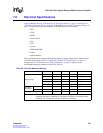
5.12 Clocks
The IXF1104 system interface has several reference clocks, including the following:
• SPI3 data path input clocks
• RGMII input and output clocks
• MDIO output clock
• JTAG input clock
• I
2
C clock
• LED output clock.
This section details the unique clock source requirements.
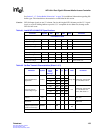
5.12.1 System Interface Reference Clocks
The following system interface clock is required by the IXF1104:
• CLK125
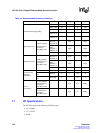
Figure 34. Line Side Interface Loopback Path
RX FIFO
SPI3 Interface
Block
TX
RX
Line Side
Interface
MAC
TX FIFO
B3230-01
Line Side Internal Loopback