


IXF1104 Quad-Port 10/100/1000 Mbps Ethernet Media Access Controller
94 Datasheet
Document Number: 278757
Revision Number: 007
Revision Date: March 25, 2004
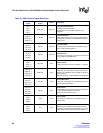
Table 26. GMII Interface Signal Definitions
IXF1104
Signal
GMII Standard
Signal
Source Description
TXC_0
TXC_1
TXC_2
TXC_3
GTX_CLK IXF1104
Transmit Reference Clock:
125 MHz for Gigabit operation.
MII operation for 10/100 Mbps operation is not
supported.
TXD[7:0]_0
TXD[7:0]_1
TXD[7:0]_2
TXD[7:0]_3
TXD[7:0] IXF1104
Transmit Data Bus:
Width of this synchronous output bus varies with the
speed/mode of operation. In 1000 Mbps mode, all 8
bits are used.
TX_EN_0
TX_EN_1
TX_EN_2
TX_EN_3
TX_EN IXF1104
Transmit Enable:
Synchronous input that indicates Valid data is being
driven on the TXD[7:0] data bus.
TX_ER_0
TX_ER_1
TX_ER_2
TX_ER_3
TX_ER IXF1104
Transmit Error:
Synchronous input to PHY causes the transmission of
error symbols in 1000 Mbps links.
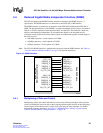
RXC_0
RXC_1
RXC_2
RXC_3
RX_CLK PHY
Receive Clock:
Continuous reference clock is 125 MHz +/– 100 ppm.
RXD[7:0]_0
RXD[7:0]_1
RXD[7:0]_2
RXD[7:0]_3
RXD<3:0> PHY
Receive Data Bus:
Width of the bus varies with the speed and mode of
operation. In 1000 Mbps mode, all 8 bits are driven by
the PHY device.
Note: MII operation at 10/100 Mbps is not supported.
RX_DV_0
RX_DV_1
RX_DV_2
RX_DV_3
RX_DV PHY
Receive Data Valid:
This signal is asserted when valid data is present on
the corresponding RXD bus.
RX_ER_0
RX_ER_1
RX_ER_2
RX_ER_3
RX_ER PHY
Receive Error:
In 1000 Mbps mode, asserted when error symbols or
carrier extension symbols are received.
Always synchronous to RX_CLK.
CRS_0
CRS_1
CRS_2
CRS_3
CRS PHY
Carrier Sense:
Asserted when valid activity is detected at the line-
side interface.
COL_0
COL_1
COL_2
COL_3
COL PHY
Collision:
Asserted when a collision is detected and remains
asserted for the duration of the collision event. In full-
duplex mode, the PHY should force this signal Low.