


IXF1104 4-Port Gigabit Ethernet Media Access Controller
40 Datasheet
Document Number: 278757
Revision Number: 007
Revision Date: March 25, 2004
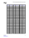
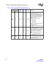
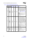
TMOD1
TMOD0
NA
D9
A6
Input
3.3 V
LVTTL
TMOD[1:0] Transmit Word Modulo.
32-bit Multi-PHY mode: TMOD[1:0]
indicates the valid data bytes of TDAT[31:0].
During transmission, TMOD[1:0] should
always be “00” until the last double word is
transferred on TDAT[31:0]. TMOD[1:0]
specifies the valid bytes of TDAT when
TEOP is asserted:
TMOD[1:0] – Valid Bytes of TDAT
00 =4 bytes [31:0]
01 =3 bytes [31:8]
10 =2 bytes [31:16]
11 =1 byte [31:24]
TENB must be asserted simultaneously for
TMOD[1:0] to be valid.
4 x 8 Single-PHY mode: MOD[1:0] is not
required.
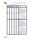
TSX NA E1 Input
3.3 V
LVTTL
Transmit Start of Transfer.
32-bit Multi-PHY mode: TSX asserted with
TENB = 1 indicates that the PHY address is
present on TDAT[7:0]. The valid values on
TDAT[7:0] are 3, 2, 1, and 0. When
TENB = 0, TSX is not used by the PHY
device.
NOTE: Only TDAT[1:0] are relevant; all
other bits are “Don’t Care”.
4 x 8 Single-PHY mode: TSX is not used.
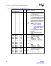
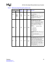
TADR1
TADR0
TADR1
TADR0
A12
A11
Input
3.3 V
LVTTL
TADR[1:0] Transmit PHY Address.
The value on TADR[1:0] selects one of the
PHY ports that drives the PTPA signal after
the rising edge of TFCLK.
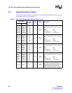
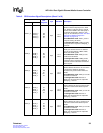
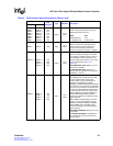
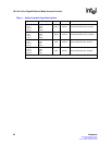
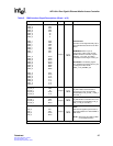
Table 3. SPI3 Interface Signal Descriptions (Sheet 3 of 8)
Signal Name
Ball
Designator
Type Standard Description
MPHY SPHY