


IXF1104 4-Port Gigabit Ethernet Media Access Controller
Datasheet 53
Document Number: 278757
Revision Number: 007
Revision Date: March 25, 2004
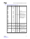
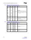
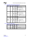
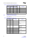
TX_FAULT_INT P23
Open
Drain
Output*
2.5 V
CMOS
Transmitter Fault Interrupt.
TX_FAULT_INT is an open drain interrupt output
that signals a TX_FAULT condition.
NOTE: An external pull-up resistor is
required for proper operation.
NOTE: *Dual-mode I/O
Normal operation: Open drain output
Boundary Scan Mode: Standard CMOS
output
MOD_DEF_INT N22
Open
Drain
Output*
2.5 V
CMOS
Module Definition Interrupt.
MOD_DEF_INT is an open drain interrupt output
that signals a MOD_DEF condition.
NOTE: An external pull-up resistor is
required for proper operation.
NOTE: *Dual-mode I/O
Normal operation: Open drain output
Boundary Scan Mode: Standard CMOS
output
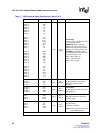
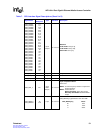
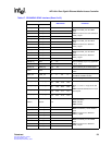
I
2
C_CLK L23 Output
2.5 V
CMOS
I
2
C_CLK is the clock used for the I
2
C bus
interface.
I
2
C DATA_0
I
2
C DATA_1
I
2
C DATA_2
I
2
C DATA_3
L24
M24
N24
P24
Input/
Open
Drain
Output*
2.5 V
CMOS
I
2
C Data Bus.
I
2
C DATA_0:3 are the data I/Os for the I
2
C bus
interface.
NOTE: An external pull-up resistor is
required for proper operation.
NOTE: *Dual-mode I/O
Normal operation: Input/ open drain
output
Boundary Scan Mode: Standard CMOS
output
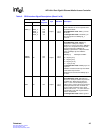
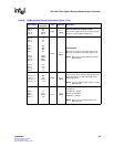
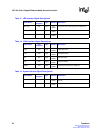
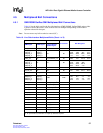
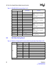
Table 10. MDIO Interface Signal Descriptions
Signal Name
Ball
Designator
Type Standard Description
MDIO V21
Input/
Output
2.5 V
CMOS
MDIO is the management data input and output.
NOTE: An external pull-up resistor is required for
proper operation.
MDC W24 Output
2.5 V
CMOS
MDC is the management clock to external devices.
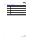
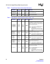
Table 9. Optical Module Interface Signal Descriptions (Sheet 2 of 2)
Signal Name
Ball
Designator
Type Standard Description