


IXF1104 4-Port Gigabit Ethernet Media Access Controller
Datasheet 57
Document Number: 278757
Revision Number: 007
Revision Date: March 25, 2004
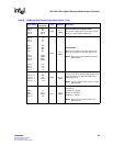
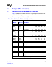
4.5 Multiplexed Ball Connections
4.5.1 GMII/RGMII/SerDes/OMI Multiplexed Ball Connections
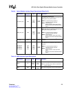
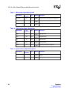
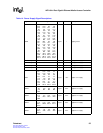
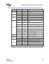
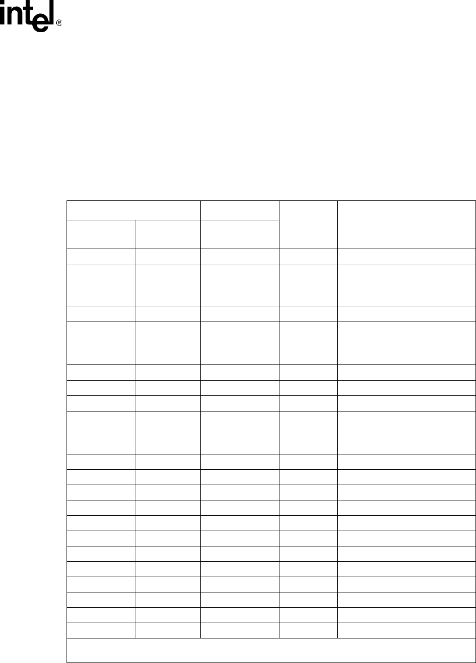
Table 16 lists the balls used for the line-side interfaces (GMII, RGMII, SerDes/OMI) and provides
a guide to connect these balls. Some of these balls are multiplexed depending on the mode of
operation selected for that port.
Note: Do not connect any balls marked as unused (NC).
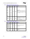
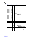
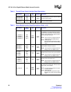
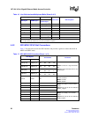
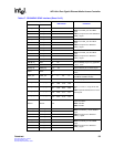
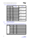
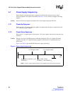
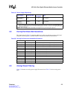
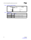
Table 16. Line Side Interface Multiplexed Balls (Sheet 1 of 2)
Copper Mode Fiber Mode
Unused Port Ball Designator
GMII Signal RGMII Signal
Optical Module/
SerDes Signal
TXC_0:3 TXC_0:3 NC NC AA1 AD7 AC20 AB14
TXD[3:0]_0
TXD[3:0]_1
TXD[3:0]_2
TXD[3:0]_3
TD[3:0]_0
TD[3:0]_1
TD[3:0]_2
TD[3:0]_3
NC NC
AA3
AD9
AB23
V17
Y3
AB9
AB22
V16
Y2
AB7
AB21
V15
Y1
AC7
AB20
V14
TXD4_0:3 NC TX_DISABLE_0:3
2
NC AB3 AA7 AD16 AA14
TXD[7:5]_0
TXD[7:5]_1
TXD[7:5]_2
TXD[7:5]_3
NC NC NC
Y4
AC9
AA18
W14
AB4
AD8
AA20
AA16
AC3
AB8
AB19
Y15
TX_EN_0:3 TX_CTL_0:3 NC NC AB2 Y8 AC22 V12
TX_ER_0:3 NC NC NC W1 AD6 AD17 AB13
RXC_0:3 RXC_0:3 GND GND V4 AD11 AA24 V23
RXD[3:0]_0
RXD[3:0]_1
RXD[3:0]_2
RXD[3:0]_3
RD[3:0]_0
RD[3:0]_1
RD[3:0]_2
RD[3:0]_3
GND GND
Y7
W9
Y23
W18
W7
W11
Y22
Y19
V7
Y11
Y21
Y18
V8
Y9
Y20
Y17
RXD4_0:3 GND MOD_DEF_0:3
1
GND Y6 AD10 W22 T16
RXD5_0:3 GND TX_FAULT_0:3
1
GND Y5 AC11 V20 T17
RXD6_0:3 GND RX_LOS_0:3
1
GND AB5 AA11 V19 T18
RXD7_0:3 GND GND GND AC5 Y10 W20 T19
RX_DV_0:3 RX_CTL_0:3 GND GND V5 AB11 Y24 V18
RX_ER_0:3 GND GND GND W5 Y12 AA22 U20
CRS_0:3 GND GND GND AA5 AA9 AB15 AC16
COL_0:3 GND GND GND AB6 AB10 AD15 AB17
GND GND RX_P_0:3 GND P22 V22 T24 U24
GND GND RX_N_0:3 GND R22 U22 R24 V24
NC NC TX_P_0:3 NC Y13 AD13 W16 AC18
NC NC TX_N_0:3 NC Y14 AD14 Y16 AD18
1. An external pull-up resistor is required with most optical modules.
2. An open drain I/O, external 4.7 k Ω pull-up resistor is required.