


IXF1104 Quad-Port 10/100/1000 Mbps Ethernet Media Access Controller
Datasheet 125
Document Number: 278757
Revision Number: 007
Revision Date: March 25, 2004
Note: There is a restriction when using this loopback mode. At least one clock cycle is required between
a TEOP assertion and a TSOP assertion. This is required when the pre-pend feature of the receive
FIFO is enabled to allow the addition of the extra two bytes to the data sent on the transmit
interface. Where the pre-pend feature has not been enabled, data can be sent back-to-back on the
transmit SPI3 interface with TSOP following TEOP on the next cycle.
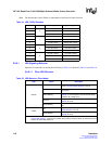
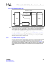
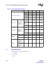
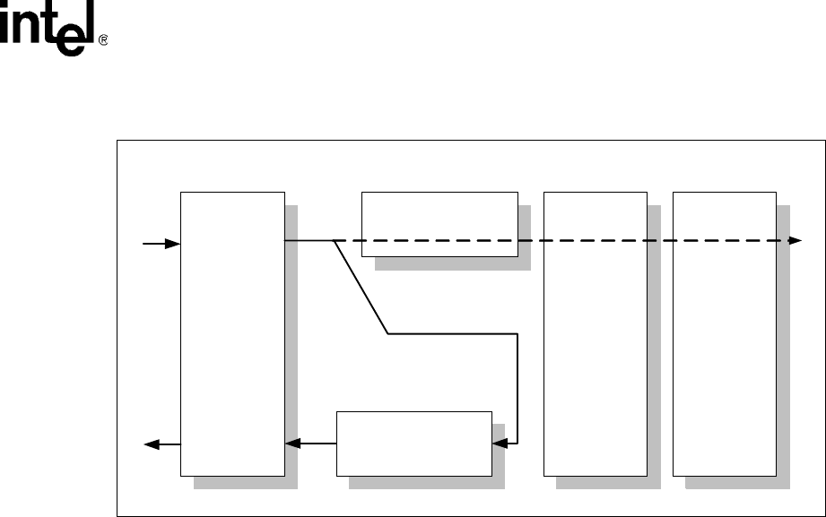
To configure the IXF1104 to use the SPI3 loopback mode, the “RX FIFO SPI3 Loopback Enable
for Ports 0 - 3 ($0x5B2)" must be configured. Each IXF1104 port has a unique bit in this register
designated to control loopback. It is possible to have individual ports in a loopback mode while
other ports continue to operate in a normal mode.
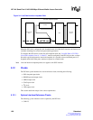
5.11.2 Line Side Interface Loopback
To provide a diagnostic loopback feature on the line-side interfaces, the IXF1104 can be configured
to loop back any data received by the IXF1104 through one of the line interfaces back to the
corresponding transmit line interface. This is done by using the data path shown in Figure 34. The
line-side interface can be either SerDes, RGMII or GMII. Please note that it is not possible to loop
one line-side interface back to a different one (for example, Rx SerDes looped back to transmit
RGMII).
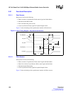
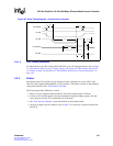
Figure 33. SPI3 Interface Loopback Path
SPI3 Interface
Block
TX
RX
Line Side
Interface
MAC
TX FIFO
RX FIFO
B3229-01
SPI3 Internal Loopback