


IXF1104 Quad-Port 10/100/1000 Mbps Ethernet Media Access Controller
118 Datasheet
Document Number: 278757
Revision Number: 007
Revision Date: March 25, 2004
Note: The data decode of the LED bits is independent of the Physical mode selection.
5.8.6.1 LED Signaling Behavior
Operation in each mode for the decoded LED data in Table 34 is detailed in Table 35 and Table 36.
5.8.6.1.1 Fiber LED Behavior
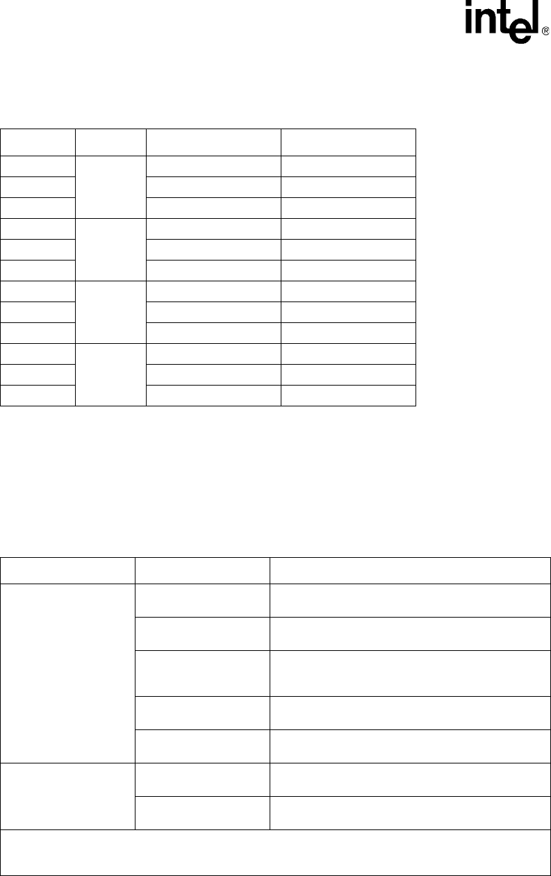
Table 34. LED_DATA# Decodes
LED_DATA# MAC Port # Fiber Designation Copper Designation
1
0
Rx LED—Amber Link LED—Amber
2 Rx LED—Green Link LED—Green
3 TX LED—Green Activity LED—Green
4
1
Rx LED—Amber Link LED—Amber
5 Rx LED—Green Link LED—Green
6 TX LED—Green Activity LED—Green
7
2
Rx LED—Amber Link LED—Amber
8 Rx LED—Green Link LED—Green
9 TX LED—Green Activity LED—Green
10
3
Rx LED—Amber Link LED—Amber
11 Rx LED—Green Link LED—Green
12 TX LED—Green Activity LED—Green
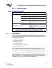
Table 35. LED Behavior (Fiber Mode)
Type Status Description
RXLED
Off
Synchronization occurs but no packets are received
and the “Link LED Enable ($0x502)” is not set.
Amber On
RX Synchronization has not occurred or no optical
signal exists.
Amber Blinking
The port has remote fault and the “Link LED Enable
($0x502)” is not set (based on remote fault bit setting
received in Rx_Config word).
Green On
RX Synchronization occurs and the “Link LED Enable
($0x502)” bit is set.
Green Blinking
RX Synchronization occurs and the port is receiving
data.
TXLED
Off
The port is not transmitting data or the “Link LED
Enable ($0x502)” is not set.
Green Blinking
The port is transmitting data and the “Link LED Enable
($0x502)” bit is set
NOTE: Table 35 assumes the port is enabled in the “Port Enable ($0x500)” and the LEDs are enabled in the
“LED Control ($0x509)”. If a port is not enabled, all the LEDs for that port will be off. If the LEDs are not
enabled, all of the LEDs will be off.