


IXF1104 4-Port Gigabit Ethernet Media Access Controller
134 Datasheet
Document Number: 278757
Revision Number: 007
Revision Date: March 25, 2004
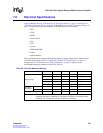
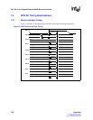
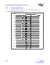
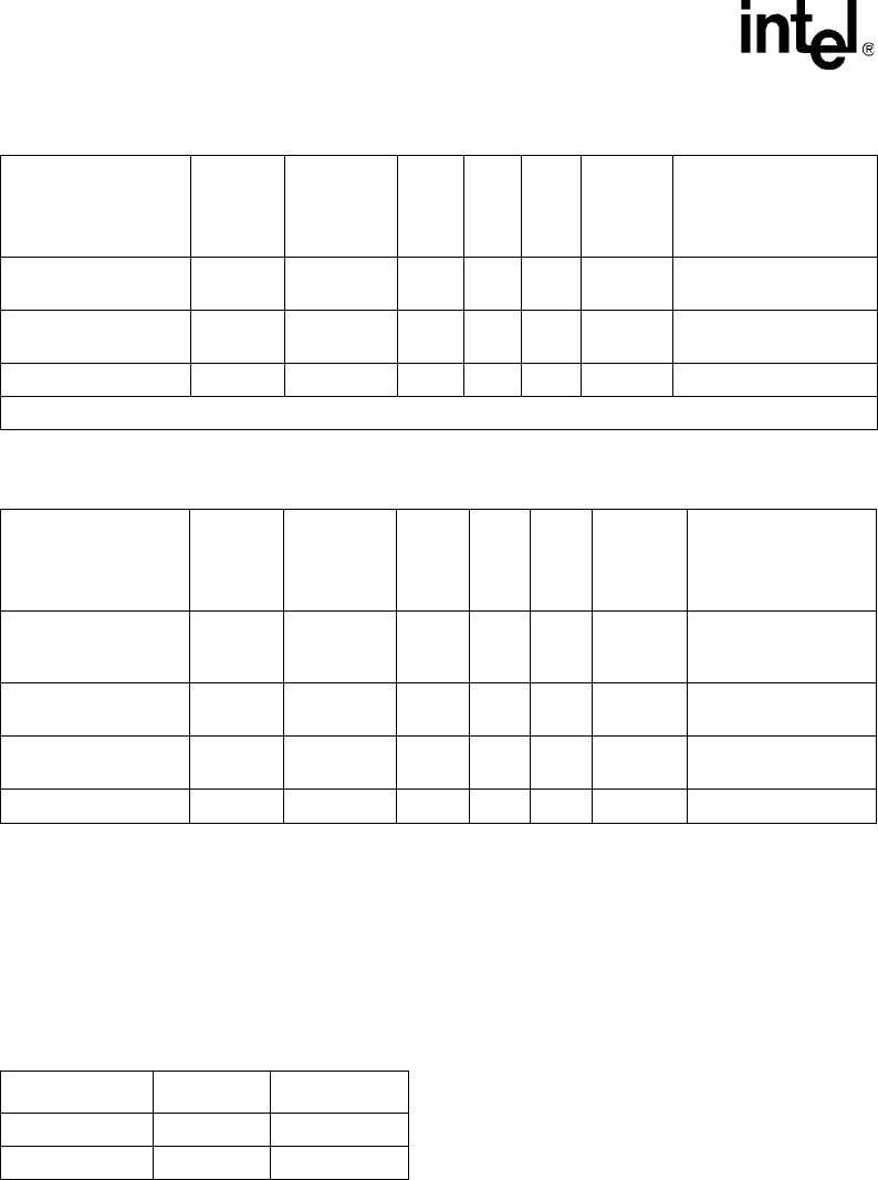
7.1.1 Undershoot / Overshoot Specifications
The overshoot figures given in this section represent the maximum voltage that can be applied
without affecting the reliability of the device (see Table 44).
Caut ion: If these limits are exceeded, damage to the device will occur.
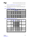
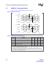
7.1.2 RGMII Electrical Characteristics
The RGMII signals (including MDIO/MDC) are based on 2.5V CMOS interface voltages, as
defined by JEDEC EIA/JESD8-5 (see Table 45).
Receiver common
mode voltage range
RxCMV – 900 1275 1650 mV –
Receiver termination
impedance
RxZ – 40 51 62.5
Ω –
Signal detect level RxSigDet – 50 125 200 mVp-pdiff –
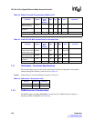
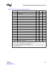
Table 43. Intel® IXF1104 MAC SerDes Receive Characteristics
Parameter Symbol
Normalized
Power
Drive
Settings
Min Typ Max Units Comments
Receiver differential
voltage requirement at
center of receive eye
RxDiffV – 200 – – mVp-p diff –
Receiver common
mode voltage range
RxCMV – 900 1275 1650 mV –
Receiver termination
impedance
RxZ – 40 51 62.5
Ω –
Signal detect level RxSigDet – 50 125 200 mVp-pdiff –
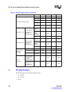
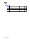
Table 42. SerDes Transmit Characteristics (Sheet 2 of 2)
Parameter Symbol
Normalized
Power
Drive
Settings
1
Min Typ Max Units Comments
1. Refer to Section 5.6.2.2, “Transmitter Programmable Driver-Power Levels” on page 103.
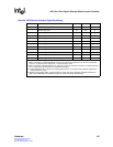
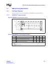
Table 44. Undershoot / Overshoot Limits
Pin Type Undershoot Overshoot
2.5 V CMOS -0.60 V 3.9 V
3.3 V LVTTL -0.60 V 3.9 V