


IXF1104 Quad-Port 10/100/1000 Mbps Ethernet Media Access Controller
86 Datasheet
Document Number: 278757
Revision Number: 007
Revision Date: March 25, 2004
5.2.2.3 Clock Rates
In MPHY mode, the TFCLK and RFCLK can be independent of each other. TFCLK and RFCLK
should be common to the IXF1104 and the Network Processor. The IXF1104 requires a single
clock source for the transmit path and a single clock source for the receive path.
To allow all four IXF1104 ports to operate at 1 Gbps, the IXF1104 is designed to allow this
interface to be overclocked. This allows operation for data transfer at data rates of up to 4.256 Gbps
when operating at an overclocked frequency of 133 MHz.
Note: MPHY mode operates at a maximum clock frequency of 133 MHz (TFCLK and RFCLK).
5.2.2.4 Parity
The IXF1104 can be odd or even (the IXF1104 is odd by default) when calculating parity on the
data bus. This can be changed to accommodate even parity if desired, and can be set for transmit
and receive independently. The RX Parity is set in bit 12 of the “SPI3 Receive Configuration
($0x701)” and the TX Parity is set in bit 4 of the “SPI3 Transmit and Global Configuration
($0x700)”.
5.2.2.5 SPHY Mode
The SPHY operation mode is selected when bit 21 of the Table 146 “SPI3 Transmit and Global
Configuration ($0x700)” on page 212 is set to 1. The SPHY mode is the default operation for the
IXF1104 SPI3 interface.
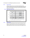
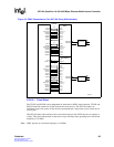
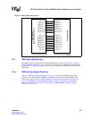
5.2.2.5.1 Data Path
The IXF1104 SPI3 interface has four 8-bit data paths that can support four independent 8-bit point-
to-point connections in SPHY mode (see Figure 16). Since each MAC port has its own dedicated
8-bit SPI3 data bus, each port has it own status signal (unlike MPHY). See the For a detailed list of
all the signals refer to the SPI3 pin multiplexing table....
Furthermore since each port has it own dedicated bus the in band port addressing is not needed.
The 8 bit data bus eliminates the need to have separate control signals determine the number of
valid bytes on an EOP.Therefore TSX, RSX, TMOD[1:0] RMOD[1:0] are not used in SPHY mode.
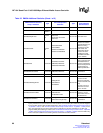
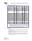
Note: See Table 17 “SPI3 MPHY/SPHY Interface” on page 58 for a complete list of the SPHY mode
signals. Unlike MPHY mode, each port has a dedicated control signal associated with each of the
per-port 8-bit data buses. Table 3 “SPI3 Interface Signal Descriptions” on page 38 provides signal
descriptions for all SPI3 signals.
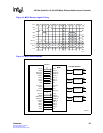
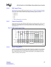
5.2.2.5.2 Receive Data Transmission
Packets are transmitted on each port as they become available from the RX FIFO. The burst length
is determined by the setting of per port burst size and the B2B pause settings in the “SPI3 Receive
Configuration ($0x701)". If the B2B pause setting is zero pause cycles inserted, then the entire
packet will be burst without any pauses unless the Network Processor de-asserts RENB. If the
B2B_Pause setting calls for the insertion of two pause cycles on a port, these are inserted after each
data burst for that port. The data bursts are user configurable for each port in the “SPI3 Receive
Configuration ($0x701)".