E6581528
E-37
5
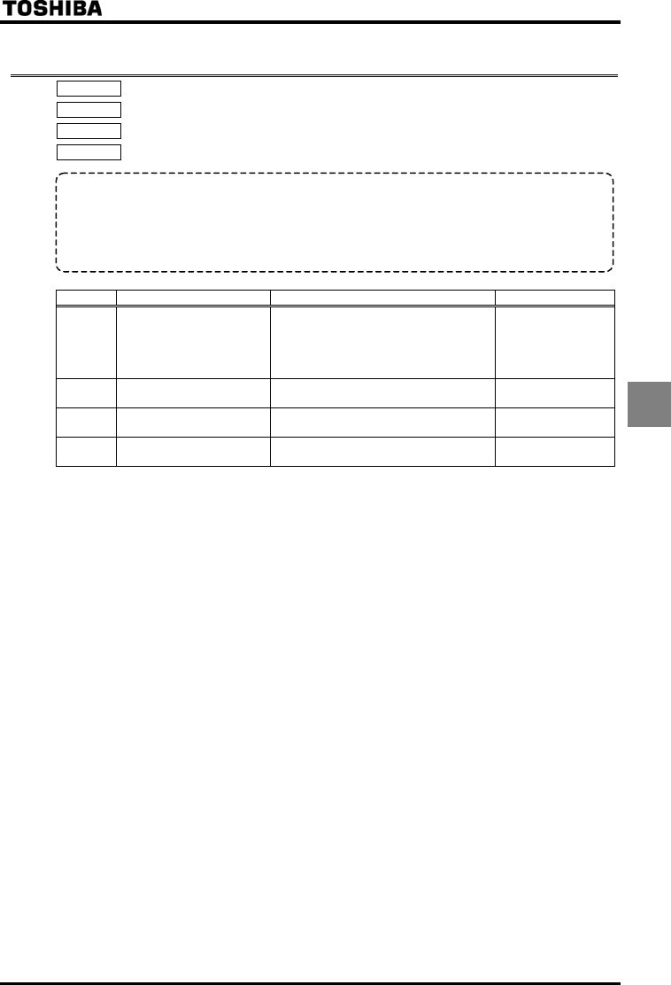
5.19 Dynamic (regenerative) braking - For abrupt motor stop
: Dynamic braking selection
: Dynamic braking resistance
: Allowable continuous braking resistance
: Braking resistance overload time
[Parameter setting]
Title Function Adjustment range Default setting
Dynamic braking selection
:Disabled
:Enabled (bracking resistance overload
detect)
:Enabled (bracking resistance overload
not detect)
Dynamic braking resistance ~ Ω
According to model
⇒ Refer to page K-46.
Allowable continuous braking
resistance
~ kW
According to model
⇒ Refer to page K-46.
Braking resistance overload
time
~ sec.
* Protection levels defined by (Refer to Section 6.14.2).
Note 1: The time set using is the time for which the resistor sustains an overload. (Enter the time elapsed
before the inverter trips if a load 10 times as large as the allowable continuous braking resistance specified
using is applied.) There is no need to change resistance settings recommended by Toshiba (except
DGP resistance setting).
Note 2: If the parameter is set to or (regenerative braking selected), the inverter will be set automatically so
as to deal with the regenerative energy from the motor by means of a resistor, without taking any action to
limit overcurrent. (The same function as =)
Note 3: For inverters with ratings of VFAS1-6200KPC or more, set to , because separate dynamic braking
units are not included as standard equipment.
• Function
Dynamic braking is used in the following cases:
1) Need to stop the motor quickly.
2) The inverter trips because of an overvoltage (OP) during deceleration.
3) Fluctuation of load condition causes a regenerative power even at a constant speed such as press machine.


