


E6581528
B-7
2
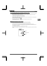
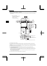
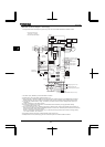
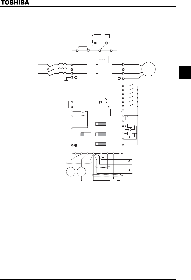
[Standard connection diagram - source logic]
The figure below shows an example of typical wiring in the main circuit VFAS1-5015PM to 5075PM and VFAS1-6022PL to
6900PL inverter.
4.
5.
6.
76
86
96
%%
4;
4;
59
59
59
59
.1
+062.%
44
Ქ
Ყ
176
21
(.#
(.$
57
%%
(.%
176
176
(/ #/
%%#
4:
445
8+++
22
/%%$
2# 2$ 2%
(
22.%
4
4'5
5
5
5
294
01
%%
+/
Ქ
Ყ
O#
*1
PFL
*3
*2
*9
*8
*7
Control
circuit
Main
circuit
Noise
filter
*4
Main circuit power source
500/575V class :
1.5(2HP)~75kW(100HP)
690V class :
Three-phase 500~690V-50/60Hz
*5
*6 *6 *6
(a)
(a)
From (a)
(a)
(a)
Voltage signal:-10~+10V
Voltage signal:0~10V
or current signal:4 (0)~20mA
External potentiometer
(or voltage signal between RR/S4 and CCA:0~10V)
Motor
Ammeter or voltmeter
Ammeter
Frequency
meter
(a)
Forward run signal
Reverse run signal
Reset
Preset speed 1
Preset speed 2
Preset speed 3
Default settings
Three-phase 500~600V-50/60Hz
2.2~90kW
*1: AC reactor (PFL) : option( if used).
*2: The DC reactor is built in for models VFAS1-6022PL to 6900PL. VFAS1-5015PM to 5075PM do not have DC reactor.
*3: The EMC filter is built in for models VFAS1-6022PL and above. The Basic filter is built in for models VFAS1-5015PM and
above.
*4: External braking resistor (option). Dynamic braking drive circuit built-in (GTR7) as standard for models 160kW or smaller.
*5: ⇒ Refer to Section 2.3.2 for chip switch functions.
*6: The functions assigned to terminals OUT1, VI/II and RR/S4 can be switched by changing parameter settings.
⇒ For details refer to Section 2.3.2.
*7: To supply control power from an external power supply for backing up the control power supplied from the inverter, an
optional control power backup device (CPS002Z) is required. In such a case, the backup device is used at the same time
with the internal power supply of the inverter.
To back up control power, set the parameter (Control power supply backup option failure monitoring) properly.
⇒ For more information, refer to 6.33.24.
*8: For PWR connection conforming to safety standards, refer to Section 9.3.