


E6581528
B-12
2
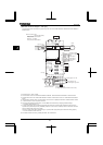
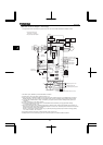
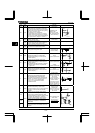
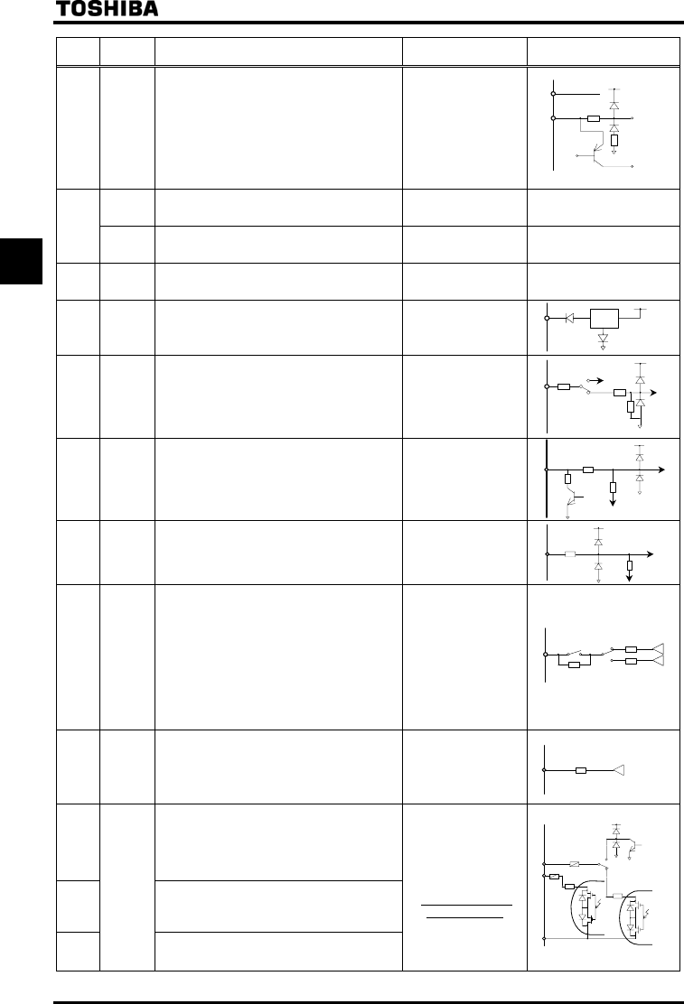
Terminal
symbol
Input/
output
Function (Sink Source logic)
Electrical
specifications
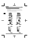
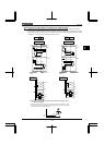
Inverter internal circuits
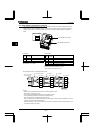
PWR Input
PWR is the Power Removal safety function.
When PWR is not connected to the 24V/PLC,
the motor cannot be started. And if it is opened
between the 24V/PLC and PWR during driving
the motor, it coasts to a stop.
This terminal is not a multifunction
programmable input terminal. It is a terminal
with the power removal function that complies
with SIL II of the safety standard IEC61508 and
the requirements for category 3 of EN954-1.
Regardless of the
setting of SW1
ON: DC17V or more
OFF: Less than DC2V
(OFF: Coast stop)
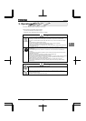
Output
24Vdc power output (when SW1 is in any
position other than PLC)
24V internal output terminal
24Vdc-200mA -
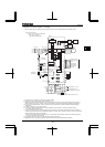
P24/
PLC
Input
If SW1 is turned to the PLC position, this
terminal can be used as a common terminal
when an external power supply is used.
- -
CC *1
Common
to input/
output
Digital signal equipotential (0V) terminal for the
control circuit and equipotential (0V) terminal for
an optional control power supply backup.
- -
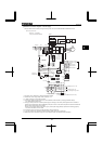
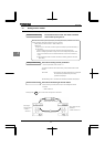
PP Output Analog input setting power output
10Vdc
(Permissible load
current:10mAdc)
RR/S4 Input
SW3: Multifunction programmable analog input
terminal when SW3 is in the RR position.
Standard default setting:0~10Vdc input and
0~60Hz frequency.
10Vdc
(Internal impedance:30 kΩ)
VI/I I Input
Multifunction programmable analog input.
Standard default setting: 0~10Vdc input and
0~60Hz frequency.
This terminal can also be used as a 4-20mAdc
(0-20mAdc) input terminal, if the parameter
set to .
10Vdc
(Internal impedance:30 kΩ)
4~20mA
(Internal impedance:242Ω)
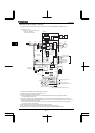
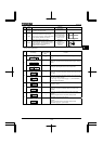
RX Input
Multifunction programmable analog input.
Standard default setting:0~±10Vdc input and
0~±60Hz frequency.
10Vdc
(Internal impedance:22 kΩ)
FM Output
Multifunction programmable analog output.
Standard default setting: output frequency
Use this terminal to connect a 1mAdc full-scale
ammeter. This terminal can also be used as a
0-10V (
=) or 0-20mA terminal
(
=), if the SW2 switch is set to
0-10V/0-20mA side.
1mA full-scale DC
ammeter (Allowable load
resistance 7.5kΩ or less)
or 7.5Vdc-1mA full-scale
DC voltmeter
0-10V full-scale DC
voltmeter (Allowable load
resistance 500Ω or
more)/0-20mA (4-20mA)
Full-scale DC ammeter
voltmeter (Allowable load
resistance 500Ω or less)
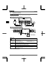
AM Output
Multifunction programmable analog output.
Standard default setting: output current
Use this terminal to connect a 1mAdc full-scale
ammeter or 7.5Vdc (10Vdc)-1mA full-scale
voltmeter.
1mA full-scale DC
ammeter ammeter
(Allowable load
resistance 7.5kΩ or less)
or 7.5Vdc-1mA full-scale
DC voltmeter
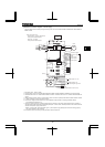
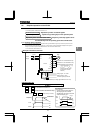
OUT1
Multifunction programmable open collector
output. The default setting is to output a signal
when output low speed threshold has been
reached. Depending on the SW4 setting, pulses
are output with frequencies of 1.00kHz to
43.20kHz. Standard default setting:3.84kHz
OUT2
Multifunction programmable open collector
output. By default, it is set to output a signal
indicating the completion of acceleration or
deceleration.
NO
Output
Digital output signal equipotential (0V) terminal
for the control circuit. It is isolated from the CC
terminal.
Open collector output
24Vdc-50mA
*Sink logic/source
logic switchable
P15
15k
7k
P5
15k
15k
242
S4
P5
R
R
SW3
12.7k
2.2k
15k
20
P24
OUT1
OUT2
SW4 PULS
LO
20
NO
15V
C
ons
t
an
t
voltage
circuit
P5
27k
10k
PWR
P24/PLC
SW2
+
-
+
-
4.7k
120
70
0-1mA
0-10V
0-20mA
4.7
k
+
-