E6581528
E-14
5
Base frequency
voltage 1
Output voltage
[V]/[%]
Output frequency [Hz]
Base frequency 1
0
VF1
VF2
VF3
VF4
VF5
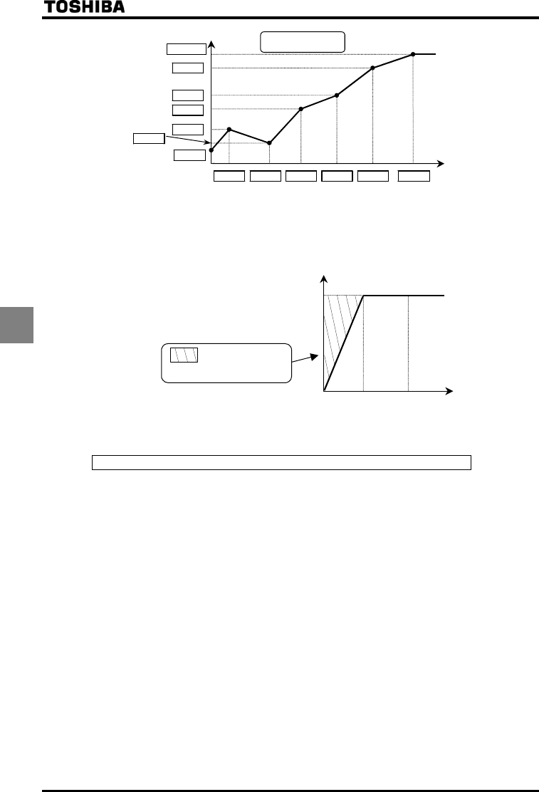
V/f 5-point setting
Note 1: Restrict the amount of torque to boost () to 3% or so. Boosting the torque too much may impair the
linearity between points.
Note 2: If the V/f 5-point is set within the diagonally shaded area in the figure below, the V/f 5-point is placed
automatically on the boundary line (heavy line in the figure).
: Area in which the
V/f 5-point cannot
be set
Voltage
Frequency
0
×
0.4413
100%
6) Operating the motor at periodic speeds by means of a motor speed
sensor
Setting for V/f control mode selection = (PG feedback control)
Set to to operate the motor at periodic speeds.
A PG feedback device (optional) is needed. In addition, a motor with a speed sensor (encoder) should be used.
Use this setting when operating a motor two or more ranks lower in capacity than the inverter at periodic speeds.
Note that the accuracy obtained by = is lower than that obtained by setting to . Also, should be set
to to perform torque control. cannot be set to in such a case.
Output torque decreases considerably in regenerative low speed operation (motor slip frequency or less). Set to
if regenerative low speed torque is necessary.
Motor constant must be set.
The motor constant can be set in any of the following two ways:
1) Automatic setting
Enter the following information that is indicated on the motor nameplate, and then execute the auto-tuning 1
command (Set to , and then reset to .).
<Information indicated on motor nameplate>
(Base frequency), (Base frequency voltage), (Motor rated capacity), (Motor rated
current), (Motor rated rotational speed) ⇒ Refer to 6.22 selection 1.
2) Manual setting
Set each motor constant manually. ⇒ Refer to 6.22 selection 2.


